
Page 324 - ABB_Motor _Protection_and_Control_catalogue_20221216
P. 324
3/248 ABB MOTOR PROTECTION AND CONTROL
—
Contactors for capacitor switching
AC-6b utilization category according to IEC 60947-4-1
Capacitor transient conditions
In Low Voltage industrial installations, capacitors are mainly used for reactive energy correction (raising the power factor). When
03
these capacitors are energized, overcurrents of high amplitude and high frequencies (3 to 15 kHz) occur during the transient period
(1 to 2 ms).
The amplitude of these current peaks, also known as "inrush current peaks", depends on the following factors:
• The network inductances.
• The transformer power and short-circuit voltage.
• The type of power factor correction.
There are 2 types of power factor correction: fixed or automatic.
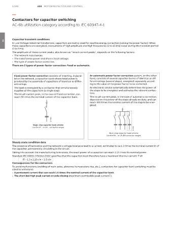
Fixed power factor correction consists of inserting, in paral- An automatic power factor correction system, on the other
lel on the network, a capacitor bank whose total power is hand, consists of several capacitor banks of identical or dif-
provided by the assembly of capacitors of identical or differ- ferent ratings (several steps), energized separately accord-
ent ratings. ing to the value of the power factor to be corrected.
The bank is energized by a contactor that simultaneously An electronic device automatically determines the power of
supplies all the capacitors (a single step). the steps to be energized and activates the relevant contac-
The inrush current peak, in the case of fixed correction, can tors.
reach 30 times the nominal current of the capacitor bank. The inrush current peak, in the case of automatic correction,
depends on the power of the steps already on duty, and can
reach 100 times the nominal current of the step to be ener-
gized.
E1178D
Single-step capacitor bank scheme
Use the AF... or UA... contactor ranges
E1179D
Multi-step capacitor bank scheme
Use the UA... or UA..RA contactor ranges.
Steady state condition data
The presence of harmonics and the network's voltage tolerance lead to a current, estimated to be 1.3 times the nominal current In of
the capacitor, permanently circulating in the circuit.
Taking into account the manufacturing tolerances, the exact power of a capacitor can reach 1.15 times its nominal power.
Standard IEC 60831-1 Edition 2002 specifies that the capacitor must therefore have a maximum thermal current IT of:
IT = 1.3 x 1.15 x In = 1.5 x In
Consequences for the contactors
To avoid malfunctions (welding of main poles, abnormal temperature rise, etc.), contactors for capacitor bank switching must be
sized to withstand:
• A permanent current that can reach 1.5 times the nominal current of the capacitor bank.
• The short but high peak current on pole closing (maximum permissible peak current Î ).