Page 959 - ABB_Motor _Protection_and_Control_catalogue_20221216
P. 959

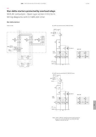
ABB  MOTOR PROTECTION AND CONTROL                                               13/69

          —

          Star-delta starters protected by overload relays
          With AF contactors - Open type version in kit form
          Wiring diagrams with CT-ERS.21S timer


          Star-delta starters

          Power circuit                                           AC or DC local control with CT-ERS.21S timer

                                                                    KM3:5/L3
                                                                    Us
                                                                   A
                                                                RESET       95
                                                                   M
                                                                 STOP       96  FR1
                       1/L1  3/L2  5/L3  1/L1  3/L2  5/L3  1/L1  3/L2  5/L3
                    A1            A1             A1
                KM1            KM3            KM2
                    A2            A2             A2                    .3
                       2/T1  4/T2  6/T3  2/T1  4/T2  6/T3  2/T1  4/T2  6/T3  KM1  I
                                                                       .4
             A
          RESET                                                           KM2  .3
             M     95  97                                                        15  A1
                            FR1                                             .4  KT1     CT-ERS.21S
            TEST   96  98                                                        16  A2         With VM
            STOP       2/T1  4/T2  6/T3                            With
                                                                   VEM4    01    01               KM2  21  KM3  21
                                                                          (2)      (2)
                                                                                                    22     22
                           W1      W2                                 A1                           A1     A1
                            V1     V2                               KM1 A2  KM3 A2  (1)  A2  KM2  KM3 A2  A2  KM2
                            U1     U2

                                                                 Us
                                                                 N
                           W1      W2                               KM3:3/L2
                            V1     V2                                  L    ∆  (3)  Y
                            U1     U2


                                                                  AC or DC remote control with CT-ERS.21S timer
                                                                   KM3:5/L3
                                                                   Us
                                                                  A
                                                               RESET        95
                                                                  M
                                                                 STOP       96  FR1
                                                                         0
                                                                       .3
                                                                     KM1  I
                                                                       .4
                                                                            .3
                                                                          KM2    15  A1
                                                                            .4          CT-ERS.21S
                                                                               KT1
                                                                                 16  A2         With VM
                                                                  With
                                                                  VEM4     01    01                 21     21
                                                                          (2)      (2)            KM2    KM3
                                                                                                    22     22
                                                                      A1                           A1     A1
                                                                    KM1  KM3        KM2          KM3         KM2
                                                                      A2   A2  (1)  A2             A2     A2
                                                                                                                      13

                                                                 Us
                                                                 N

                                                                 KM3:3/L2
                                                                       L    ∆  (3)  Y
                                                                  Note:  - VEM4 = VM4 (1) + VE4 (2) with A2-A2 (3) connection
                                                                      (Except for coil Uc 12-20 V DC : use VM4 with CA4).
                                                                      - coil Uc 12-20 V DC : A1+, A2-
   954   955   956   957   958   959   960   961   962   963   964