Page 123 - Contactors_Catalogue
P. 123

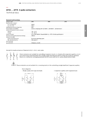
ABB  MOTOR CONTROL AND PROTECTION FOR ROLLING STOCK APPLICATIONS                 3/71

          —

          AF45 … AF75  4-pole contactors
          Technical data


          General technical data
          Contactor types                   AF45                   AF50                  AF75
          Rated insulation voltage Ui
           acc. to IEC 60947-4-1            1000 V
           acc. to UL / CSA                 600 V
          Rated impulse withstand voltage Uimp.  8 kV
          Electromagnetic compatibility     Devices complying with IEC 60947-1 / EN 60947-1 - Environment A
          Ambient air temperature close to contactor                                                                  03
           Operation                        -40...+70 °C
           Storage                          -60...+80 °C
          Climatic withstand                acc. to IEC 60068-2-30 and 60068-2-11 - UTE C 63-100 specification II
          Maximum operating altitude (without derating)  3000 m
          Mechanical durability
           Number of operating cycles       10 millions operating cycles
           Max. switching frequency         300 cycles/h
          Shock withstand
          acc. to IEC 61373                 Category 1, class B


          Remark for 4-pole contactors fitted with 2 N.O. + 2 N.C. main poles

          1    R3  R5   7
                            These contactors are suitable for controlling 2 separate circuits, i.e. 2 loads with 2 separate supplies, or 1 cir-
                            cuit comprising 2 separate loads with a single supply (see diagrams below). When the contactor operates
                            there is no mechanical overlapping between the N.O. poles and the N.C. poles: BREAK before MAKE.
          2    R4  R6   8

                   !
                        These contactors are not suitable for a reversing starter or for controlling a single load from 2 separate supplies.

                               B  l  o  c  k     d  i  a  g  r  a  m  s
                               – Single supply and 2 separate loads        – 2 separate supplies and 2 separate loads
                                                                                   Main
                                       Supply
                                                                                   supply
                                                                                   Back-up
                                                                                    supply
                               A1  1  R3  R5  7                            A1  1  R3  R5  7
                               A2  2  R4  R6  8                            A2  2  R4  R6  8
                                        Load                                        Load
                                        Load                                        Load


                                                                                                                 1SBC100145S0201
   118   119   120   121   122   123   124   125   126   127   128