
Page 261 - Contactors_Catalogue
P. 261
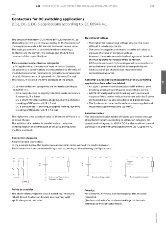
ABB  MOTOR CONTROL AND PROTECTION FOR ROLLING STOCK APPLICATIONS                 4/61

          —

          Contactors for DC switching applications
          DC-1, DC-3, DC-5 applications according to IEC 60947-4-1


                                                              Operational voltage
          The circuit switching on DC is more difficult than on AC, as
          alternating current go to zero according to the frequency of     - The higher the operational voltage value is, the more
          the supply source while DC current has a continuous value.   difficult it is to break the arc.
          The main parameters to be considered for selecting a     - The use of main poles connected in series will allow to
          contactor are the current, the voltage and the L/R time   increase the value of switched voltage.
          constant of the controlled load.                       However, the maximum switched voltage must be within
                                                                 the max operational voltage of the contactor.
          Time constant and utilization categories               All the poles required for breaking must be connected in
          In DC applications, the nature of load to switch (resistor,   series between the load and the source polarity not
          inductance or a combination) is characterized by the ratio of   linked to earth (or chassis) (see recommended
          the inductance to the resistance (L (inductance of operated   connection diagrams).
          circuit) / R (resistance of operated circuit) = mH/Ω = ms)
          This ratio L/R is called the time constant of the circuit.  ABB offer a large choice of possibilities for DC switching
                                                              applications (see selection tables):                    04
          DC current utilization categories are defined according to     - AF..(Z)B 3-pole or 4-pole contactors with either 1- pole
          IEC 60947-4-1:                                         breaking or breaking with poles connected in series.
              - DC-1 non inductive or slightly inductive loads, resistance     - GAF75..RT designed for DC breaking with permanent
            furnaces (L/R ≤ 1 ms)                                magnets fitted on the main poles for use with the 3 poles
              - DC-3 shunt motors: starting, plugging, inching, dynamic   connected in series and considered as 1-pole devices.
            breaking of DC motors (L/R ≤ 2 ms)                    - The 3 poles are connected in series via two supplied and
              - DC-5 series motors: starting, plugging, inching, dynamic   fitted insulated connections (25 mm²).
            breaking of DC motors (L/R ≤ 7.5 ms).
                                                              Selection tables
          The higher the time constant value is, the more difficult it is   The enclosed selection tables will guide your choice through
          to break the arc.                                   all contactor variants according to utilization category, for
          The addition of a resistor in parallel with an inductive   operational voltage up to 1000 V DC-1 and operational current
          winding helps in the elimination of the arcs, by reducing    up to 520 A in ambient temperatures from -25 °C up to 40 °C.
          the time constant.

          Connection diagrams
          Recommended connection
          In the example below, the 3 poles are connected in series without the load in between.
          This connection is recommended in systems according to the following configurations.


          +         -


                                    Indirect earthed system        Direct earthed system      Centre earthed system
                                    (isolated system)
                  Load

          Points to consider                                  Polarity:
          The above relates to power circuit switching. The SCPD   For all GAF75..RT types, connection polarities must be
          (Short-Circuit Protection Device) must comply with   respected.
          applicable protection rules.                        (See instruction leaflet and see markings on the main
                                                              terminals or the contactor front).


                                                                                                                 1SBC100193S0201