
Page 390 - Din prodcuts 2020
P. 390
4/36 ELECTRICAL INSTALL ATION SOLUTIONS FOR BUILDINGS 2CHC 420 001 C0201
—
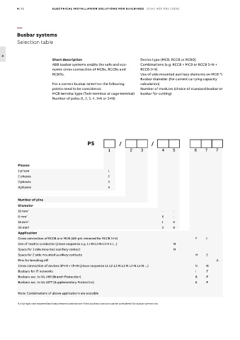
Busbar systems
Selection table
4
Short description Device type (MCB, RCCB or RCBO)
ABB busbar systems enable the safe and eco- Combinations (e.g. RCCB + MCB or RCCB 3+N +
nomic cross connection of MCBs, RCCBs and RCCB 1+N)
RCBOs. Use of side mounted auxiliary elements on MCB *)
Busbar diameter (for current carrying capacity
For a correct busbar selection the following calculation)
points need to be considered: Number of modules (choice of standard busbar or
MCB terminal type (Twin terminal or cage terminal) busbar for cutting)
Number of poles (1, 2, 3, 4, 1+N or 3+N)
PS / /
1 2 3 4 5 6 7 7
Phases
1 phase 1
2 phases 2
3 phases 3
4 phases 4
Number of pins
Diameter
10 mm 2 - -
6 mm 2 6 -
16 mm 2 1 6
30 mm 2 3 0
Application
Cross connection of RCCB and MCB (4th pin removed for RCCB 3+N) F I
Use of neutral conductor (phase sequence e.g. L1-N-L2-N-L3-N-L1...) N
Space for 1 side mounted auxiliary contact H
Space for 2 side mounted auxiliary contacts H 2
Pins for breaking off A
Cross connection of devices 3P+N + 1P+N (phase sequence L1-L2-L3-N-L1-N-L2-N-L1-N-...) N N
Busbars for IT networks I T
Busbars acc. to UL 489 (Branch Protection) B P
Busbars acc. to UL 1077 (Supplementary Protection) S P
Note: Combinations of above applications are possible
*) only right side mounted auxiliary elements and bottom fixed auxiliary contacts can be considered for busbar connection