
Page 13 - Changeover switch
P. 13
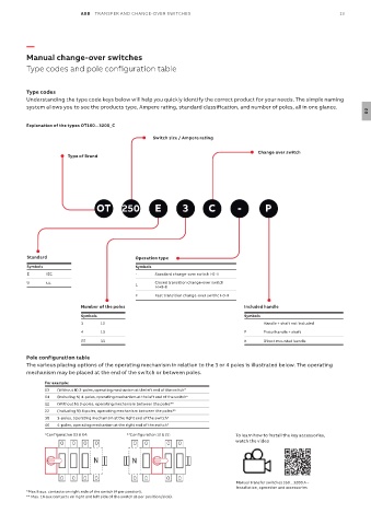
ABB  TRANSFER AND CHANGE-OVER SWITCHES                                             13


          —
          Manual change-over switches

          Type codes and pole configuration table


          Type codes
          Understanding the type code keys below will help you quickly identify the correct product for your needs. The simple naming
          system allows you to see the products type, Ampere rating, standard classification, and number of poles, all in one glance.
                                                                                                                       02

          Explanation of the types OT160...3200_C
                                                  Switch size / Ampere rating

                                                                                    Change over switch
                       Type of Brand


                                OT      250        E        3       C        -        P


          Standard                          Operation type
          Symbols                            Symbols
          E     IEC                          -     Standard change-over switch I-0-II
          U     UL                           L     Closed transition change-over switch
                                                   I-I+II-II
                                             F     Fast transition change-over swithc I-0-II
                           Number of the poles                                 Included handle
                           Symbols                                             Symbols
                           3     12                                                   Handle + shaft not included
                           4     13                                            P      Pistol handle + shaft
                           22    33                                            K      Direct mounted handle

          Pole configuration table
          The various placing options of the operating mechanism in relation to the 3 or 4 poles is illustrated below. The operating
          mechanism may be placed at the end of the switch or between poles.
               For example:
               03  (Without N) 3-poles, operating mechanism at the left end of the switch*
               04  (Including N) 4-poles, operating mechanism at the left end of the switch*
               12  (Without N) 3-poles, operating mechanism between the poles**
               22  (Including N) 4-poles, operating mechanism between the poles**
               30  3-poles, operating mechanism at the right end of the switch*
               40   4-poles, operating mechanism at the right end of the switch*
               *Configuration 03 & 04:    **Configuration 12 & 22:           To learn how to install the key accessories,
                                                                             watch the video

                               N           N


                                                                             Manual transfer switches 160…3200 A –
                                                                             Installation, operation and accessories
          *Max 8 aux. contacts on right side of the switch (4 per postion).
          ** Max. 16 aux contacts on right and left side of the switch (8 per position/side).