
Page 764 - ABB_Motor _Protection_and_Control_catalogue_20221216
P. 764
6/26 ABB MOTOR PROTECTION AND CONTROL
—
TF140DU thermal overload relays – 66 to 142 A
Technical data
Main circuit – Utilization characteristics according to IEC/EN
Type TF140DU / TF140DU-V1000
Standards IEC/EN 60947-1, IEC/EN 60947-4-1, IEC/EN 60947-5-1
Rated operational voltage Ue 690 V AC, 440 V DC
Rated frequency DC, 50/60 Hz
Frequency range 0 ... 400 Hz
Trip class 10A
Number of poles 3
Duty time 100%
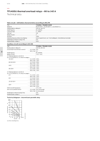
Operating frequency without early tripping Up to 15 operations/h, see "Technical diagram – Intermittent periodic duty"
Rated impulse withstand voltage Uimp 8 kV
Rated insulation voltage Ui 690 V
Auxiliary circuit according to IEC/EN
Type TF140DU / TF140DU-V1000
Rated operational voltage Ue 500 V AC, 440 V DC
Conventional free air thermal current Ith N.C., 95-96 10 A
N.O., 97-98 6 A
Rated frequency DC, 50/60 Hz
06
Number of poles 1 N.O. + 1 N.C.
Ie / Rated operational current AC-15
acc. to IEC/EN 60947-5-1 for utilization category
110-120 V N.C., 95-96 3.00 A
N.O., 97-98 1.50 A
220-230-240 V N.C., 95-96 3.00 A
N.O., 97-98 1.50 A
440 V N.C., 95-96 1.00 A
N.O., 97-98 1.00 A
480-500 V N.C., 95-96 1.00 A
N.O., 97-98 1.00 A
Ie / Rated operational current DC-13
acc. to IEC/EN 60947-5-1 for utilization category
24 V N.C., 95-96 1.25 A
N.O., 97-98 1.25 A
60 V N.C., 95-96 0.25 A
N.O., 97-98 0.25 A
110-120-125 V N.C., 95-96 0.25 A
N.O., 97-98 0.25 A
250 V N.C., 95-96 0.12 A
N.O., 97-98 0.04 A
Minimum switching capacity 17 V / 3 mA
Short-circuit protective device N.C., 95-96 10 A, fuse type gG
N.O., 97-98 6 A, fuse type gG
Rated impulse withstand voltage Uimp 6 kV
Rated insulation voltage Ui 690 V
Technical diagram – Intermittent periodic duty
(Op/h)
140
120
100 a
switching frequency 60 t = 1.5 s
80
t = 0.5 s
a
a
t = 1 s
40
a
a
20 t = 3 s
t = 5 s
0 2CDC232004F0214
0 20 40 60 80 100 (%)
duty ratio
ta: Motor starting time