
Page 79 - Contactors_Catalogue
P. 79
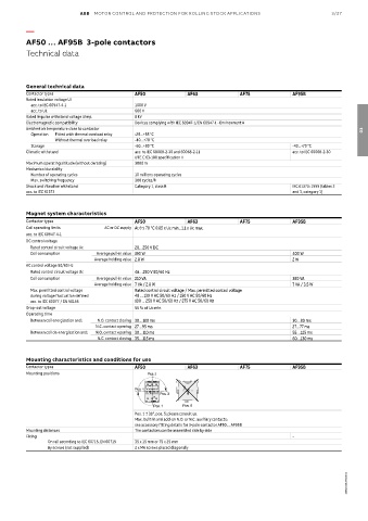
ABB  MOTOR CONTROL AND PROTECTION FOR ROLLING STOCK APPLICATIONS                 3/27

          —

          AF50 … AF95B  3-pole contactors
          Technical data


          General technical data
          Contactor types                    AF50             AF63             AF75             AF95B
          Rated insulation voltage Ui
           acc. to IEC 60947-4-1             1000 V
           acc. to UL                        600 V
          Rated impulse withstand voltage Uimp.  8 kV
          Electromagnetic compatibility      Devices complying with IEC 60947-1/EN 60947-1 - Environment A
          Ambient air temperature close to contactor                                                                  03
           Operation  Fitted with thermal overload relay  -25...+55 °C
                   Without thermal overload relay  -40…+70 °C
           Storage                           -60...+80 °C                                       -40...+70 °C
          Climatic withstand                 acc. to IEC 60068-2-30 and 60068-2-11              acc. to IEC 60068-2-30
                                             UTE C 63-100 specification II
          Maximum operating altitude (without derating)  3000 m
          Mechanical durability
           Number of operating cycles        10 millions operating cycles
           Max. switching frequency          300 cycles/h
          Shock and vibration withstand      Category 1, class B                                IEC 61373: 1999 (tables 2
          acc. to IEC 61373                                                                     and 3, category 1)


          Magnet system characteristics
          Contactor types                    AF50             AF63             AF75             AF95B
          Coil operating limits    AC or DC supply At θ ≤ 70 °C 0.85 x Uc min...1.1 x Uc max.
          acc. to IEC 60947-4-1
          DC control voltage
           Rated control circuit voltage Uc  20…250 V DC
           Coil consumption     Average pull-in value 190 W                                     400 W
                                Average holding value 2.8 W                                     2 W
          AC control voltage 50/60 Hz
           Rated control circuit voltage Uc  48…250 V 50/60 Hz
           Coil consumption     Average pull-in value 210 VA                                    350 VA
                                Average holding value 7 VA / 2.8 W                              7 VA / 3.5 W
           Max. permitted control voltage    Rated control circuit voltage / Max. permitted control voltage
           during voltage fluctuation defined    48 ... 130 V AC 50/60 Hz / 150 V AC 50/60 Hz
           acc. to IEC 60077 / EN 50155      100 ... 250 V AC 50/60 Hz / 275 V AC 50/60 Hz
          Drop-out voltage                   55 % of Uc min.
          Operating time
           Between coil energization and:  N.O. contact closing 30…100 ms                       30…80 ms
                                N.C. contact opening 27…95 ms                                   27…77 ms
           Between coil de-energization and:  N.O. contact opening 30…110 ms                    55…125 ms
                                 N.C. contact closing 35…115 ms                                 60…130 ms


          Mounting characteristics and conditions for use
          Contactor types                    AF50             AF63             AF75             AF95B
          Mounting positions  Pos. 2  +30°  -30°  Pos. 2  +30°  -30°

                     Pos. 4                  Pos. 4
                             Pos. 3                  Pos. 3
                           Pos. 1     Pos. 1 ± 30°  Pos. 5  Pos. 6        Pos. 5    Pos. 6
                                                   Pos. 1
                                                             Pos. 1 ± 30°
                                             Pos. 1 ± 30°, pos. 5: please consult us.
                                             Max. built-in and add-on N.O. or N.C. auxiliary contacts:
                                             see accessory fitting details for 3-pole contactor AF50 ... AF95B
          Mounting distances                 The contactors can be assembled side by side
          Fixing                                                                                –
                On rail according to IEC 60715, EN 60715  35 x 15 mm or 75 x 25 mm
                By screws (not supplied)     2 x M6 screws placed diagonally


                                                                                                                 1SBC100137S0201