
Page 2948 - Din prodcuts 2020
P. 2948
22/52 ELECTRICAL INSTALL ATION SOLUTIONS FOR BUILDINGS 2CHC 420 001 C0201
—
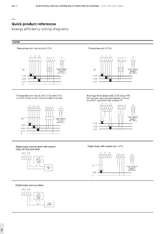
Quick product references
Energy efficiency wiring diagrams
DMTME
Three-phase with neutral and 3 CTs Three-phase with 3 CTs
Three-phase with neutral and 3 CTs
Three-phase with 3 CTs
Three-phase with neutral and 3 CTs Three-phase with 3 CTs
I1 I2 I3 I1 I2 I3 I1 I2 I3 I1 I2 I3
1
2
L3
S
AUX
2
L3
S
S2 S1 S2 S1 S S2 S1 S2 S1 S2 S1L2 L1 N L3 L2 L1 N AUX S2 S1 S2 S1 S S2 S1 S2 S1 S2 S1L2 L1 N L3 L2 L1 N AUX
1
AUX
I1 I2 I3 I1 I2 I3
S2 S1 S2 S1 S2 S1 L3 L2 L1 N AUX S2 S1 S2 S1 S2 S1 L3 L2 L1 N AUX
-
96:
-
96:
DMTME, DMTME DMTME, DMTME-96: DMTME, DMTME DMTME, DMTME-96:
115V – 230V a.c. 115V – 230V a.c. 115V – 230V a.c. 115V – 230V a.c.
DMTME-72: DMTME-72: DMTME-72: DMTME-72:
230V – 400V a.c.
230V – 400V a.c.
S2 S1 S2 S1 DMTME, DMTME-96: 230V – 400V a.c. S2 S1 S2 S1 DMTME, DMTME-96: 230V – 400V a.c.
115V – 230V a.c. 115V – 230V a.c.
S2 S1
S2 S1
L1 (R) L1 (R) S2 S1 DMTME-72: L1 (R) L1 (R) S2 S1 DMTME-72:
S2 S1 230V – 400V a.c. S2 S1 230V – 400V a.c.
L2 (S) L2 (S) S2 S1 S2 S1 L2 (S) L2 (S) S2 S1 S2 S1
L1 (R) S2 S1 L1 (R) S2 S1
L3 (T) L3 (T) S2 S1 L3 (T) L3 (T) S2 S1
L2 (S) L2 (S)
N N
L3 (T) L3 (T)
N
Three-phase with neutral and 3 CTs and 3 VTs
Aron type three-phase with 2 CTs and 2 VTs
Three-phase with neutral and 3 CTs and 3 VTs Aron type three-phase with 2 CTs and 2 VTs
Up to 500 V Up to 500 V phase-neutral a direct connection is possible With symmetric and unbalanced network, 3 CTs and
neutral a direct connection is possible
-
phase
With symmetric and unbalanced network, 3 CTs and
Three-phase with neutral and 3 CTs and 3 VTs Aron type three-phase with 2 CTs and 2 VTs
up to 800 V, beyond this value must use VT.
up to 800 V, beyond this value must use VT.
Up to 500 V phase-neutral a direct connection is possible With symmetric and unbalanced network, 3 CTs and
I1
I3
I3
I2
I1
I2
up to 800 V, beyond this value must use VT.
I1 I2 I3 I1 I2 I3 S2 S1 S2 S1 S S2 S1 S2 S1 S2 S1L2 L1 N L3 L2 L1 N AUX
L3
1
2
S
AUX
2
S
L3
1
S2 S1 S2 S1 S S2 S1 S2 S1 S2 S1 L2 L1 N L3 L2 L1 N AUX I1 I2 I3
AUX
I1 I2 I3 S2 S1 S2 S1 S2 S1 L3 L2 L1 N AUX
S2 S1 S2 S1 S2 S1 L3 L2 L1 N AUX
DMTME, DMTME - DMTME, DMTME-96:
9
6:
TV DMTME, DMTME - DMTME, DMTME-96: 115V – 230V a.c. 115V – 230V a.c.
TV
96
:
DMTME-72:
115V – 230V a.c. 115V – 230V a.c. DMTME, DMTME-96: DMTME-72:
DMTME-72: DMTME-72: S2 S1 S2 S1 230V – 400V a.c. 230V – 400V a.c.
115V – 230V a.c.
230V – 400V a.c.
S2 S1 S2 S1 TV DMTME, DMTME-96: 230V – 400V a.c. L1 (R) L1 (R) DMTME-72:
115V – 230V a.c.
L1 (R) L1 (R) S2 S1 DMTME-72: S2 S1 S2 S1 S2 S1 230V – 400V a.c.
S2 S1
S2 S1 230V – 400V a.c. L2 (S) L2 (S)
L1 (R)
L2 (S) L2 (S) S2 S1 S2 S1
L1 (R) S2 S1 L3 (T) L3 (T) S2 S1
L3 (T) L3 (T) L2 (S)
L2 (S) S2 S1
N N L3 (T)
L3 (T)
N
Single phase with neutral and 1 CTs
Digital output used as alarm with external Single phase with neutral and 1 CTs
Digital output used as alarm with external
relays for load command
relays for load command Single phase with neutral and 1 CTs
Digital output used as alarm with external
relays for load command I1 I2 I3 I1 I2 I3
OUT2
OUT1
OUT1
OUT2
S2 S1 S2 S1 S2 S1 L2 L1 N
AUX
1 2 1 2 1 2 1 2 S2 S1 S2 S1 S2 S1 L3 L3 L2 L1 N AUX
OUT2 OUT1 V aux V aux I1 I2 I3
1 2 1 2 48V a.c./ 48V a.c./ S2 S1 S2 S1 S2 S1 L3 L2 L1 N AUX
d.c. max d.c. max
V aux
100mA 100mA
48V a.c./
d.c. max
100mA
96:
-
External External DMTME, DMTME DMTME, DMTME-96:
relay relay 115V – 230V a.c. 115V – 230V a.c.
DMTME-72:
DMTME-72:
230V – 400V a.c.
S2 S1 S2 S1 DMTME, DMTME-96: 230V – 400V a.c.
External
relay L1 (R) L1 (R) 115V – 230V a.c.
DMTME-72:
S2 S1 230V – 400V a.c.
N
L1 (R) N
N
Digital output used as pulses
Digital output used as pulses
Digital output used as pulses
OUT1
OUT2
OUT1
OUT2
1 2 1 2 1 2 1 2
OUT2 OUT1 V aux V aux
1 2 1 2 48V a.c./ 48V a.c./
d.c max d.c max
V aux
100mA 100mA
48V a.c./
d.c max
100mA
Pulse Pulse
adquisition adquisition
Pulse
adquisition
22