
Page 302 - Din prodcuts 2020
P. 302
2/110 ELECTRICAL INSTALL ATION SOLUTIONS FOR BUILDINGS 2CHC 420 001 C0201
—
2
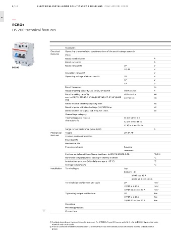
RCBOs
DS 200 technical features
DS 200 AC DS 200 A DS 200 M AC DS 200 M A
Standards IEC/EN 61009-1; IEC/EN 61009-2-1; IEC/EN 60947-2
Electrical Operating characteristic: type (wave form of the earth leakage sensed) AC A AC A
features Poles 2P, 3P, 4P
Rated sensitivity IDn A 0.03
Rated current In A 6 ≤In ≤ 63
Rated voltage Ue 2P V 230-240
DS 200
3P, 4P V 230/400 - 240/415
Insulation voltage Ui V 500
Operating voltage of circuit test Ut 2P V 110 (170 for 30 mA) - 254
3P V 195 (300 for 30 mA) - 440
4P V 195 (300 for 30 mA) - 440
Rated frequency Hz 50…60
Rated breaking capacity acc. to IEC/EN 61009 ultimate Icn A 6000 6000 10000 10000
Rated breaking capacity ultimate Icu kA 10 10 15 15
acc. to IEC/EN 60947-2 1P+N @230 VAC, 2P, 3P, 4P @400 service Ics kA 7.5 7.5 11.2 11.2
VAC
Rated residual breaking capacity I∆m kA 6 6 10 10
Rated impulse withstand voltage (1.2/50) Uimp kV 6
Dielectric test voltage at ind. freq. for 1 min. kV 2.5
Overvoltage category III, disconnector abilities
Thermomagnetic release B: 3 In ≤ Im ≤ 5 In n n n n
characteristic
C: 5 In ≤ Im ≤ 10 In n n n n
K: 10 In ≤ Im ≤ 14 In n
Surge current resistance (wave 8/20) A NA
Mechanical Toggle 2P, 3P, 4P black (MCB) sealable in ON-OFF position + blue (RCD)
features Contact position indication CPI on window
Electrical life 10000
Mechanical life 20000
Protection degree housing IP4X
terminals IP2X
Environmental conditions (damp heat) acc. to IEC/EN 60068-2-30 °C/RH 28 cycles with 55°C/90-96% and 25°C/95-100%
Reference temperature for setting of thermal element °C 30
Ambient temperature (with daily average ≤ +35 °C) °C -25…+55
Storage temperature °C -40…+70
Installation Terminal type top failsafe bidirectional cylinder-lift terminal (shock protected) b
bottom 2P failsafe bidirectional cylinder-lift terminal (shock protected) b
3P/4P In ≤ 40 A cage (shock protected)
3P/4P 50 A ≤ In ≤ 63 A failsafe bidirectional cylinder-lift terminal (shock protected) b
Terminal size top/bottom per cable 2P mm 2 rigid: 35/25 flexible: 25/25
3P/4P In ≤ 40 A mm 2 rigid: 35/25 flexible: 25/16
3P/4P 50 A ≤ In ≤ 63 A mm 2 rigid : 35/25 flexible : 25/25
Tightening torque top/bottom 2P Nm 2.8/2.8
3P/4P In ≤ 40 A Nm 2.8/1.2
3P/4P 50 A ≤ In ≤ 63 A Nm 2.8/2.8
Mounting on DIN rail EN 60715 (35 mm) by means of fast clip device
Mounting position Any
Connection 715 (35 mm) by means of fast clip devicefrom top and bottom
Available depending on type and characteristic curve. For 2P RCBOs A type B-C curves up to 32 A, refer to DS202C 2 protected poles
RCBOs in only two modules
b Prior to connection of aluminium conductors (≥ 4 mm 2 ) ensure that their contact points are cleaned, brushed and coated with
grease