Page 690 - Din prodcuts 2020
P. 690
6/58 ELECTRICAL INSTALL ATION SOLUTIONS FOR BUILDINGS 2CHC 420 001 C0201
—
Command and signaling
E 260 latching relays
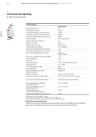
Technical features
E 260/E 260 C
Rated load at 250 V AC 8 A
Incandescent lamp load 1000 W
Fluorescent lamp load in twin-lamp circuit 1000 W
Fluorescent lamp load shunt compensated 350 W
6
Fluorescent lamp load inductive or capacitive 500 W
Electronic ballast Ion m 70 A/10 ms b
E 260
Inductive load, cosϕ = 0.6/230 V ~ 5 A
Contact rating at DC 100 W
Minimum contact rating 4 V AC/10 mA
Contact gap/contact material 0.5 mm/Ag Sn02
Service life mecha nical switchover at 103/h > 10 7
Service life at rated load cosϕ = 1 and 103/h > 10 5
Service life with filament lamps at 103/h 800 W > 10 ,
5
1000 W > 0.8x10 5
Service life at rated load cosϕ = 0.6 and 103/h > 10 4
Max. switching rate 10 /h
3
Bounce time 3 ms
Connection capacity 2 x 1.5 mm with connector sleeve
2
Tightening torque 0.5 … 0.8 Nm
ON duration at rated voltage 100 %
Coil voltage range 0.9 to 1.1 Un
Minimum command time/interval 50/1000 ms
between commands
Ambient temperature -20 °C / -4 °F to 50 °C / 122 °F
Control current when controlled locally 230 V AC 115 mA, after 10s 8 mA ± 20 %
Control current when controlled centrally 230 V AC 8 mA, after 10s 3 mA ± 20 %
Max. parallel capacity of individual 0.7 µF (ca. 2000 m)
control wire at 230 V ~
Max. parallel capacity of central 0.2 µF (ca. 700 m)
control wire at 230 V ~
Max. glow lamp current 10 mA
– parallel to 230 V control buttons
Max. induced voltage at 230 V control inputs 0.2 Un
Latching relays for lamp installations on request.
E 260 C can not be used with fluorescent lamp load shunt compensated.
b In the case of electronic control gear, take into account a 40-fold inrush current.
E 260 electronic latching relays
The electronic version of latching relays guarantees maximum reliability, life, and noiseless
operation. The E 260 C version also allows centralized reset function (ON/OFF).

