
Page 730 - Din prodcuts 2020
P. 730
7/14 ELECTRICAL INSTALL ATION SOLUTIONS FOR BUILDINGS 2CHC 420 001 C0201
—
Control and automation
CT-D range
Operating controls
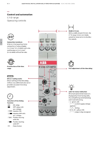
Width 17.5 mm
With a width of just 17.5 mm, the
CT-D range timers are ideally
suited for installation in distribu-
tion panels.
Connection terminals
7
Wide terminal spacing makes
connection of wires simpler:
2 x 1.5 mm² (2 x 16 AWG) with wire
end ferrules or 2 x 2.5 mm²
(2 x 14 AWG) without ferrules.
Preselection of the time
range Fine adjustment of the time delay
Direct reading scales
Direct setting of the time delay
without any additional calculation
provides accurate time delay
adjustment.
LEDs for status indication
All actual operational states are
displayed by front-facing LEDs,
thus simplifying commissioning
and troubleshooting.
Selection of the timing
function • U - green LED:
V control supply voltage
A ON-delay applied /
B OFF-delay with W timing
aux. voltage • R, R1, R2 - yellow LED:
CA Impulse-ON
V output relay energized
CB Impulse-OFF with
aux. voltage
DA Flasher starting
with ON
DB Flasher starting
with OFF
H Pulse former