Page 9 - DIN Disconnectors
P. 9

9


          —

          Electronic Fuse Monitoring

          3-pole


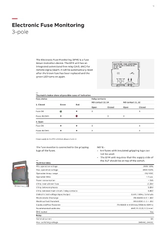
                           The Electronic Fuse Monitoring (EFM) is a fuse
                           blown indication device. The EFM unit has an
                           integrated potentional free relay (1NO, 1NC) for                          1SEB000018
                           remote signal/alarm. It will be automatically reset
                           after the blown fuse has been replaced and the
                           green LED turns on again.


                           —
                           The matrix below show all possible cases of indication
                           Fuse status                              Relay contacts
                                                                   NO contact 13, 14     NO contact 11, 12
                           1. Closed        Green      Red
                                                                   Open       Closed     Open        Closed
                           Fuse OK                                 X                                 X
                           Fuses BLOWN                                        X          X

                           2. Open
                           Fuse OK                                 X                                 X
                           Fuses BLOWN                             X                                 X


                           Power supply to the EFM unit from phase L2 and L3

                           The fuse monitor is connected to the gripping   NOTE :
                           lugs of the fuses.                          •  NH fuses with insulated gripping lugs can
                                                                         not be used.
                                                                       •  The EFM unit requires that the supply side of
                           —                                             the XLP should be on top of the switch.
                           Technical data
                           Min. operation voltage                                                       290V -10%
                           Max. operation voltage                                                      690V +10%
                           Operation temp. range                                                         -25/+80C
                           Operation time                                                                 < 2 sec.
                           Power consumption                                                               < 3VA
                           Uimp. over a blown fuse                                                         12,3kV
                           Uimp. between phases                                                            9,8kV
                           Uimp. between main circuit / relay contacts                                     9,8kV
                           Dielectric test voltage input/output                                3,5kV / 50Hz / 1 minute
                           Electrostatic Discharge                                               EN 61000-4-2 +- 4kV
                           Electrical Fast Transient                                             EN 61000-4-4 +- 4kV
                           Conducted Fast Transient                                  EN 61000-4-6 10Vrms/150kHz-80MHz
                           Recommended cable size                                              AWG 22-12/0,2-2,5 mm 2
                           EMC tested                                                                        Yes
                           Relay:
                           Nominal current                                                                   8A
                           Max. switching voltage                                                   240VAC, 24VDC
   4   5   6   7   8   9   10   11   12   13   14