Page 13 - V16 Catalogue Final
P. 13

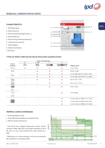
RESIDUAL CURRENT DEVICE (RCD)


        CHARACTERISTICS
                                                                                                                  DIN MCB &
                                                                                                        6        LOADCENTRES
        1.  RCD Model Name                                 9
        2.  Rated Current (I )                             1                                            3
                     n
        3.  Rated Residual Operating Current (I )          2 4
                                   Δn
        4.  Rated Voltage (U )                             5
                      n
        5.  Rated Making & Breaking Capacity (I )
                                    m
        6.  Contact Position Indicator
                                                           7
        7.  Wiring Diagram
                                                           8
        8.  ABB Identity Number
        9. Test Button


        TYPES OF WAVE FORM DETECTED BY RCDS AND CLASSIFICATION

                                           Proper functioning type
                            AC           A / APR         F             B
             Current
            waveform                                                             Tripping current
                             ▪             ▪             ▪             ▪         0.5 to 1.0 IΔn

                             _             ▪             ▪             ▪         0.35 to 1.4 IΔn
                             _             ▪             ▪             ▪         Current delay angle 90°: 0.25 to 1.4 IΔn
                             _             ▪             ▪             ▪         Current delay angle 135°:0.11 to 1.4IΔn
                                           ▪             ▪             ▪
                             _                                                   max. 1.4 IΔn + 6 mA
                             _             _             ▪             ▪         max. 1.4 IΔn + 10 mA

                             _             _             ▪             ▪         0.5 to 1.4 IΔn


                             _             _             _             ▪         0.5 to 2.0 IΔn


                                                                       ▪
                             _             _             _                       Current frequency 150Hz: 0.5 to 2.4 IΔn
                             _             _             _             ▪         Current frequency 400 Hz: 0.5 to 6 IΔn
                             _             _             _             ▪         Current frequency 1000Hz: 0.5 to14 IΔn


        TRIPPING CURVE COMPARISON

        •  30 mA instantaneous RCD
        •  30 mA APR (anti-disturbance) instantaneous RCD
        •  300 mA selective RCD (type S)


        * Type S RCDs have a delayed tripping action and are installed
        upstream of other rapid RCDs to guarantee selectivity and limit
        the power out only to the portion of the system affected by a
        fault.
        * APR devices which trip according to the limit times allowed by
        the Standards for instantaneous RCDs.


        Phone: 1300 556 601                            www.ipd.com.au                               V16-PD-DIN-R05  5
   8   9   10   11   12   13   14   15   16   17   18