Page 15 - Product-catalogue-v17
P. 15

Circuit Breakers & Load Centres


        RESIDUAL CURRENT DEVICE (RCD)
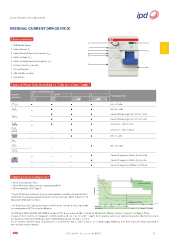

         Characteristics
                                                               9                                         6
         1.  RCD Model Name
                                                               1                                                    1
         2.  Rated Current (I )                                2                                         3
                     n
         3.  Rated Residual Operating Current (I )             4
                                   Δn
                                                               5
         4.  Rated Voltage (U )
                      n
         5.  Rated Making & Breaking Capacity (I )
                                    m
         6.  Contact Position Indicator                        7
                                                                                                         8
         7.  Wiring Diagram
         8.  ABB Identity Number
         9.  Test Button
         Types of Wave form Detected by RCDs and Classification


                       Proper functioning type
         Current       AC            A / AP-R      F             B
         waveform                                                              Tripping current

                       ▪             ▪             ▪             ▪             0.5 to 1.0 IΔn
                       _             ▪             ▪             ▪             0.35 to 1.4 IΔn
                       _             ▪             ▪             ▪             Current Delay Angle 90°: 0.25 to 1.4 IΔn
                       _             ▪             ▪             ▪             Current Delay Angle 135°: 0.11 to 1.4 IΔn
                       _             ▪             ▪             ▪             Maximum 1.4 IΔn + 6mA

                       _             _             ▪             ▪             Maximum 1.4 IΔn + 10mA

                       _             _             ▪             ▪             0.5 to 1.4 IΔn


                       _             _             _             ▪             0.5 to 2.0 IΔn


                       _             _             _             ▪             Current Frequency 150Hz: 0.5 to 2.4 IΔn
                       _             _             _             ▪             Current Frequency 400Hz: 0.5 to 6 IΔn
                       _             _             _             ▪             Current Frequency 1000Hz: 0.5 to14 IΔn


         Tripping Curve Comparison

         •  30mA instantaneous RCD
         •  30mA AP-R (anti-disturbance) instantaneous RCD
         •  300mA selective RCD (Type S)
         * Type S RCDs have a delayed tripping action and are installed upstream of other
         rapid RCDs to guarantee selectivity and limit the power out only to the portion of
         the system affected by a fault.

         * AP-R devices which trip according to the limit times allowed by the Standards
         for instantaneous RCDs, as outlined below.
         On 30th April 2023, AS/NZS 3000:2018 Amendment No. 2 was released. That amendment included a clause relating to Type AC and Type A RCDs;
         Clause 2.6.2.2.2 starting at Paragraph 4; RCDs shall be of the type for which tripping in ensured extend to (a) residual sinusoidal alternating current,
         (b) residual sinusoidal alternating current and (c) residual pulsating direct current.
         For 24 months from the date of publication of Amendment No. 2, either Item (a) or (b) may apply. Following that time  Type AC RCDs described in
         Item (a) shall not be installed.


                                               1300 556 601  |  ipd.com.au  |  V17-R04                       15
   10   11   12   13   14   15   16   17   18   19   20