
Page 327 - 35_DS702_E_2014_Lightning_Protection_Guide
P. 327
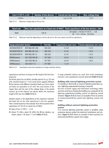
Line J-Y (ST) Y...x 0.8  Number of bus devices  Current per bus device  Max. voltage drop
                  0.8 km                  60                 e.g. 1.5 mA             5.4 V
          Table 9.12.1   Maximum voltage drop on the bus line


             Baud rate  Max. bus capacitance at a baud rate of 9600  Total capacitance of the bus devices + line
                                                                  60 meters + 0.8 km J-Y (ST) Y ... · 0.8
               9600                     100 nF
                                                                     60 · 1 nF + 0.8 km · 50 nF/km
          Table 9.12.2   Maximum baud rate depending on the bus devices (in this case meters) and the line capacitance


          Surge protective device         Part No.    Capacitance: core / core  Series impedance per core
          BLITZDUCTOR XT   BXT ML2 BD S 48  920 245          0.7 nF                 1.0 Ω
          BLITZDUCTOR XT   BXT ML2 BE S 24  920 224          0.5 nF                 1.8 Ω
          BLITZDUCTOR XT   BXT ML2 BE S 5  920 220           2.7 nF                 1.0 Ω
          DEHNconnect    DCO SD2 MD 48     917 942           0.6 nF                 1.8 Ω
          DEHNconnect    DCO SD2 ME 24     917 921           0.5 nF                 1.8 Ω
          DEHNconnect    DCO SD2 E 12      917 987           1.2 nF                   –
          Table 9.12.3   Capacitances and series impedances of surge protective devices


          capacitances and have an impact on the length of the bus line /     If surge protective devices are used, their series resistances
          baud rate.                                   and core / core capacitances must be observed (Table 9.12.3).
          An M-bus panel has an M-bus standby current of e.g. 375 mA
          (250 standard loads of 1.5 mA each) which supplies different   Building with external lightning protection system
          M-bus devices with different standard loads (e.g. three stand-  If a building is fitted with an external lightning protection sys-
          ard loads are equivalent to 4.5 mA). The cross-section of the   tem, lightning equipotential bonding is required.
          copper lines and the sum of the voltage drops in the partial   All cores of power supply and information technology cables
          sections up to the relevant bus device define the maximum   and lines entering or leaving the building are connected to the
          length of the bus line (Table 9.12.1).       lightning equipotential bonding system via lightning current
                                                       arresters. Figure 9.12.2 shows an example of how to protect
          Another aspect is the dependence of the maximum transmit-  an interconnected M-bus system from lightning currents and
          ted baud rate on the total capacitance in the bus segment.   surges.
          This is shown based on the example of an M-bus panel with a
          capacitance of 100 nF at a baud rate of 9600:  Building without external lightning protection
                                                       system
          ¨  Type of line J-Y (ST) Y… x 0.8            If no external lightning protection system is installed, surge
          ¨  About 75 Ω/km, about 50 nF/km for M-bus devices, e.g.   protective devices protect the electrical installations and sys-
            meters, about 1 nF, about 1.5 mA (Table 9.12.2).  tems. Figure 9.12.3 shows an example of how to protect an
                                                       interconnected M-bus system from surges.


          326  LIGHTNING PROTECTION GUIDE                            www.dehn-international.com