
Page 326 - 35_DS702_E_2014_Lightning_Protection_Guide
P. 326
The function of an M-bus (meter bus) is to transfer meter read- meters installed on site are collected in sub-stations and are
ings of consumption meters. Data can be centrally read off centrally transmitted to the system panel via the bus line.
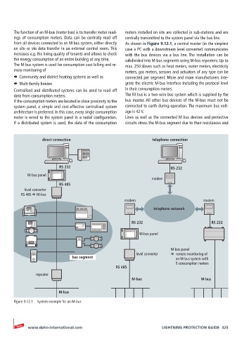
from all devices connected to an M-bus system, either directly As shown in Figure 9.12.1, a central master (in the simplest
on site or via data transfer in an external control room. This case a PC with a downstream level converter) communicates
increases e.g. the living quality of tenants and allows to check with the bus devices via a bus line. The installation can be
the energy consumption of an entire building at any time. subdivided into M-bus segments using M-bus repeaters. Up to
The M-bus system is used for consumption cost billing and re- max. 250 slaves such as heat meters, water meters, electricity
mote monitoring of meters, gas meters, sensors and actuators of any type can be
¨ Community and district heating systems as well as connected per segment. More and more manufacturers inte-
¨ Multi-family houses grate the electric M-bus interface including the protocol level
Centralised and distributed systems can be used to read off in their consumption meters.
data from consumption meters. The M-bus is a two-wire bus system which is supplied by the
If the consumption meters are located in close proximity to the bus master. All other bus devices of the M-bus must not be
system panel, a simple and cost-effective centralised system connected to earth during operation. The maximum bus volt-
architecture is preferred. In this case, every single consumption age is 42 V.
meter is wired to the system panel in a radial configuration. Lines as well as the connected M-bus devices and protective
If a distributed system is used, the data of the consumption circuits stress the M-bus segment due to their resistances and
direct connection telephone connection
RS 232 RS 232
M-bus panel
modem
RS 485
level converter
RS 485 M-bus
modem modem
telephone network
RS 232 RS 232
M-bus panel
M-bus panel
level converter remote monitoring of
bus segment an M-bus system with
5 consumption meters
RS 485
repeater
M-bus M-bus
M-bus
Figure 9.12.1 System example for an M-bus
www.dehn-international.com LIGHTNING PROTECTION GUIDE 325