
Page 414 - ABB_Motor _Protection_and_Control_catalogue_20221216
P. 414
3/338 ABB MOTOR PROTECTION AND CONTROL
—
Auxiliary contacts
Electrical durability
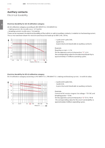
Electrical durability for AC-15 utilization category
03
AC-15 utilization category according to IEC 60947-5-1 / EN 60947-5-1:
• making current: 10 x Ie with cos ϕ = 0.7 and Ue
• breaking current: Ie with cos ϕ = 0.4 and Ue.
These curves represent the electrical durability of the built-in or add-on auxiliary contacts, in relation to the breaking current.
The curves have been drawn for resistive and inductive loads up to 690 V, 40...60 Hz.
30 • 1-pole and 4-pole CA5,
20
1-pole CC5,
10
2-pole CAL5 and CAL18 add-on auxiliary contacts.
5 3 2 Example:
Million operating cycles 0.5 1 Breaking current = 1.2 A
2.7
On the opposite curve at intersection "O" 1.2 A
the corresponding value for the electrical durability is
0.3
0.2
0.1 approximately 2.7 millions operating cycles.
0.02 0.05 0.1 0.2 0.3 0.5 1 2 3 45 6 10
1.2
Breaking current (A)
Electrical durability for DC-13 utilization category
DC-13 utilization category according to IEC 60947-5-1 / EN 60947-5-1: making and breaking current = Ie with Ue value.
• 1-pole and 4-pole CA5,
100 1-pole CC5,
70 1.10 cycles
6
50 2-pole CAL5 and CAL18 add-on auxiliary contacts.
6
3.10 cycles
Breaking power (W) 10 5 10.10 cycles Example:
20
6
Control of DC electro-magnet: Ue voltage = 72 V DC and
breaking power = 70 W.
the corresponding value for the electrical durability is
2 On the opposite curve at intersection "O" 72 V / 70 W
approximately 2 millions operating cycles.
1
10 20 24 50 72 100 200 250 500
Voltage (V)