
Page 693 - ABB_Motor _Protection_and_Control_catalogue_20221216
P. 693
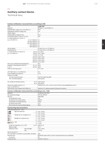
ABB  MOTOR PROTECTION AND CONTROL                                                5/43

          —

          Auxiliary contact blocks
          Technical data


          Contact utilization characteristics according to IEC
          Types                             1-pole CA3
          Standards                         IEC 60947-5-1 and EN 60947-5-1
          Rated insulation voltage Ui acc. to IEC 60947-5-1  690 V
          Rated impulse withstand voltage Uimp  6 kV
          Pollution degree                  3
          Rated operational voltage Ue max.  690 V
          Conventional thermal current Ith - θ ≤ 40 °C  10 A
          Ie / Rated operational current AC-15
          acc. to IEC 60947-5-1  24-127 V 50/60 Hz 6 A
                                220-240 V 50/60 Hz 4 A
                                400-440 V 50/60 Hz 3 A
                                   500 V 50/60 Hz 2 A                                                                 05
                                   690 V 50/60 Hz 2 A
          Making capacity                   10 x Ie AC-15 acc. to IEC 60947-5-1
          Breaking capacity                 10 x Ie AC-15 acc. to IEC 60947-5-1
          Ie / Rated operational current DC-13  24 V DC 6 A / 144 W
          acc. to IEC 60947-5-1        48 V DC 2.8 A / 134 W
                                       72 V DC 1 A / 72 W
                                      110 V DC 0.55 A / 60 W
                                      125 V DC 0.55 A / 69 W
                                      220 V DC 0.27 A / 60 W
                                      250 V DC 0.27 A / 68 W
          Short-circuit protection device gG type fuse  10 A
          Rated short-time withstand current Icw  for 1.0 s 100 A
          θ = 40 °C                    for 0.1 s 140 A
          Minimum switching capacity        12 V / 3 mA

          with failure rate acc. to IEC 60947-5-4  10-7
          Power dissipation per pole at 6 A  0.1 W
          Mechanical durability
            Number of operating cycles      10 millions operating cycles
            Max. switching frequency        3600 cycles/h

          Max. electrical switching frequency  AC-15 1200 cycles/h
                                        DC-13 900 cycles/h
          Mechanically linked contacts acc. to    Additional N.O. or N.C. auxiliary contacts (CA3) are mechanically linked contacts
          annex L of IEC 60947-5-1
          Mirror contacts acc. to annex F of IEC 60947-4-1  Additional N.C. auxiliary contacts (CA3) are mirror contacts
          Contact utilization characteristics according to UL / CSA
          Standards                         UL 508, CSA C22.2 N°14
          Max. operational voltage          690 V AC, 250 V DC
          Pilot duty                        A600, Q300
           AC thermal rated current         10 A
           AC maximum volt-ampere making    7200 VA
           AC maximum volt-ampere breaking  720 VA
           DC thermal rated current         2.5 A
           DC maximum volt-ampere making-breaking  69 VA
          Connecting characteristics
          Connection capacity (min. ... max.)
                 Rigid Solid/Stranded     1 x 0.75...2.5 mm²
                                          2 x 0.75...2.5 mm²
                 Flexible with non insulated ferrule  1 x 0.75...2.5 mm²
                                          2 x 0.75...2.5 mm²
                 Flexible with insulated ferrule  1 x 0.75...2.5 mm²
                                          2 x 0.75...1.5 mm²
                 Lugs                    L ≤ 7.7 mm
               l  L
                                          l > 3.2 mm
           Connection capacity acc. to UL / CSA  1 or 2 x AWG 18...14
           Stripping length                 9 mm
           Tightening torque  Recommended   1 Nm / 9 Ib.in
                             Max.           1.20 Nm
          Degree of protection
          acc. to IEC 60947-1 / EN 60947-1 and IEC 60529 / EN 60529  IP20
          Screw terminals                   Delivered in open position, screws of unused terminals must be tightened
           All terminals                    M3
          Screwdriver type                  Flat Ø 5.5 / Pozidriv 2