Page 695 - ABB_Motor _Protection_and_Control_catalogue_20221216
P. 695

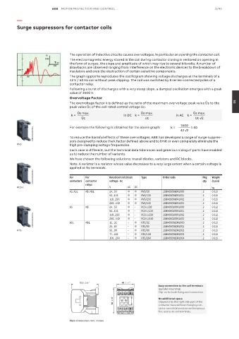
ABB  MOTOR PROTECTION AND CONTROL                                                5/45

          —

          Surge suppressors for contactor coils


                                    The operation of inductive circuits causes overvoltages, in particular on opening the contactor coil.
                         (V)
                        1000        The electromagnetic energy stored in the coil during contactor closing is restored on opening in
                            T (µs)  the form of surges, the slope and amplitude of which may rise to several kilovolts. A number of
                         0  100
                                    drawbacks are observed ranging from interference on the electronic devices to the breakdown of
          1000
                                    insulators and even the destruction of certain sensitive components.
           0  100                   The graph opposite reproduces the oscillogram showing voltage discharges at the terminals of a
                                    42 V / 50 Hz coil without peak clipping. The coil was switched by 8 series-connected poles of a
                                    contactor relay.
                                    Following a burst of discharges with a very steep slope, a damped oscillation emerges with a peak
                                    value of 3500 V.
                                    Overvoltage Factor
                                    The overvoltage factor k is defined as the ratio of the maximum overvoltage peak value Ûs to the   05
                                    peak value Ûc of the coil rated control voltage Uc:
                                        Ûs max.                        Ûs max.                   Ûs max.
                                     k =                       in DC  k =                in AC  k =
                                          Ûc                             Uc                 3500     Uc √2

                 1SBC101042F0014    For example the following is obtained for the above graph:     k =   42 √2   ≈ 60

                                    To reduce the harmful effects of these overvoltages, ABB has developed a range of surge suppres-
          RV5                       sors designed to reduce the k factor defined above and to limit or even completely eliminate the
                                    high pre-damping voltage frequencies.
                                    Each case is different, but the technical data tolerances and generous sizing of parts have enabled
                                    us to reduce the number of variants.
                                    We have chosen the following solutions: transil diodes, varistors and RC blocks.
                                    Note: A varistor is a resistor whose value decreases to a very large extent when a certain voltage is
                                    applied at its terminals.
                 1SBC101042F0014    For     For         Rated control circuit    Type   Order code    Pkg   Weight

                                                                                                           (1 pce)
                                                                                                      qty
                                    contactors
                                                        voltage - Uc
                                            contactor
          RC5-1                             relays      V        AC  DC                                    kg
                                    AS, ASL  NS, NSL    24...50  ●  ●  RV5/50     1SBN050010R1000     2    0.015
                                                        50...133  ●  ●  RV5/133   1SBN050010R1001     2    0.015
                                                        110...250  ●  ●  RV5/250  1SBN050010R1002     2    0.015
                                                        250...440  ●  ●  RV5/440  1SBN050010R1003     2    0.015
                                    AS      NS          24...50  ●  –  RC5-1/50   1SBN050100R1000     2    0.012
                                                        50...133  ●  – –  RC5-1/133  1SBN050100R1001  2 2  0.012
                 1SBC101042F0014    ASL     NSL         250...440  ●  – ●  RC5-1/440  1SBN050100R1003  2 2  0.012
                                                                       RC5-1/250
                                                                                  1SBN050100R1002
                                                                                                           0.012
                                                        110...250
                                                                 ●
                                                                                  1SBN050020R1000
                                                                       RT5/32
                                                                                                           0.015
                                                        12...32
                                                                 –
                                                        50...90
                                                                                                           0.015
                                                                                  1SBN050020R1002
                                                                       RT5/90
                                                                    ●
          RT5                                           25...65  – –  ●  RT5/65   1SBN050020R1001     2 2  0.015
                                                        77...150  –  ●  RT5/150   1SBN050020R1003     2    0.015
                                                        150...264  –  ●  RT5/264  1SBN050020R1004     2    0.015
                                         72.5  2.85"          45  1.77"        45  1.77"
                                                                                Easy connection to the coil terminals
                                                                                (parallel mounting)
                                                                                Clip-on for both fixing and connection.
                                                         68  2.68"        68  2.68"  No additional space
                                                                                Clipped onto the right side part of the
                                                                                contactor base without changing con-
                                                                                tactor overall dimensions and keeping a
                                                                                free access to coil terminals.

                                    Main dimensions mm, inches
   690   691   692   693   694   695   696   697   698   699   700