Page 879 - ABB_Motor _Protection_and_Control_catalogue_20221216
P. 879
ABB  MOTOR PROTECTION AND CONTROL                                               12/26


          —
          —
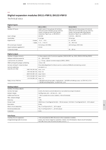
          Digital expansion modules DX111-FBP.0, DX122-FBP.0
          D i g i t a l  e x p an s i o n  m o dul e s  D X 1 1 1 - F BP . 0 ,  D X 12 2 - F BP . 0
          Technical data
          T e c h n i c al  d a t a


          Digital inputs
          Type                              DX111-FBP.0                       DX122-FBP.0
          Number of inputs                  Eight inputs in two groups of common   Eight inputs in two groups of common
                                            reference potential (One group with five   reference potential (One group with five
                                            inputs, one group with three inputs)    inputs, one group with three inputs)
                                            Insulation: Type 1 acc. to EN 61131-1  Insulation: Type 2 acc. to EN 61131-1
          Input voltage                     24 V DC                           110 V AC ... 240 V AC
          Input delay                       6 ms typ.                         20 ms typ.
          Signal levels               0 state  - 31.2 ... + 5 V               0 ... 40 V AC
                                      1 state  + 15 ... + 31.2 V              74 ... 265 V AC
          ON current per channel            6.0 mA typ. (24 V DC)             10.0 mA typ. (230 V AC)
          Input resistance against 0 V      3.9 kΩ
          Frequency range                                                     45 ... 65 Hz

          Digital output
          Number of digital outputs         4 relay outputs with 2 common supplies (1DO0 & 1DO1 by 1DOC; 2DO2 & 2DO3 by 2DOC)
          Voltage switching capacity        12 … 250 V AC/DC
          Load current via common           I max = 6 A gL / gG per common supply (1DOC, 2DOC)
          Minimum load for proper switching  1 W or 1 VA
          Contact wiring for inductive load  Free-wheeling diode for direct current, varistors/VDRs for alternating current
          Current switching                 EN 60947-5-1
          capacity per relay   240 V AC (AC-15)  max. 1.5 A
                               120 V AC (AC-15)  max. 3 A
                               250 V DC (DC-13)  max. 0.11 A
                               125 V DC (DC-13)  max. 0.22 A
                                24 V DC (DC-13)  max. 1 A
          Relay contact lifetime            > 500.000 switching cycles – mechanical, > 100.000 switching cycles – at 250 V AC, 0.5 A
                                            > 50.000 switching cycles – at 250 V AC, 1.5 A

          Analog output
          Number of analog outputs          1
          Connection type                   2-wire, for motor current indication on an external analog instrument
          Output ranges                     Configurable: 0/4 ...20 mA or 0 ... 10 V
          Cable specification               < 30 m outside the control cabinet; >30 m if shielded
          Max. output voltage               10 V
          Accuracy                          < 5%
          Output load                       500 Ω max. if configured for 0/4 ... 20 mA output; 1 k Ω min. if configured for 0 ... 10 V output
          Resolution                        8 bits
                                                                                                                      12
          Short-circuit detection           Yes, if configured for 0 ... 10 V output
          Wire break detection              Yes, if configured for 4 ... 20 mA output
          Insulation                        none

          Interfaces
          Interface for I/O expansion       1 for connection to UMC100 and/or other expansion modules
          Integrated diagnostic functions   Green LED: Device ready for operation, Yellow LED: Wire break or short circuit indication
                                            Red LED: Error (loss of communication, failure, ...)

