Page 1898 - Din prodcuts 2020
P. 1898

14/84            ELECTRICAL INSTALL ATION SOLUTIONS FOR BUILDINGS   2CHC 420 001 C0201


          —
          ABB i-bus® KNX
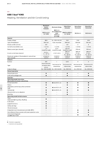
          Heating, Ventilation and Air Conditioning


                                                    Electronic
                                                     Switch   Electronic Relay  Valve Drive   Valve Drive   Valve Drive
                                                    Actuator                 Actuator    Controller   Controller
                                                                 ER/U 1.1
                                                              (in combination
                                                   ES/S x.1.2.1   with     VAA/S x.230.2.1  VC/S 4.1.1  VC/S 4.2.1
                                                     (x = 4/8)               (x = 6/12)
                                                                 US/U x.2
                                                                 (x = 2/4)
          General
          Supply voltage                              KNX     24...250 V AC/DC  KNX        KNX          KNX
          Type of installation                       DIN-Rail  Flush-mounted  DIN-Rail    DIN-Rail     DIN-Rail
          Module width (18 mm)                        4/8           –          4/8          8            8
          Current consumption, bus                   < 12 mA     < 12 mA      < 12 mA     < 12 mA      < 12 mA
                                                      1 A         0.5 A       160 mA
          Rated current (per channel)                                                     250 mA       250 mA
                                                  (resistive load)  (resistive load)  (resistive load)
                                                                              300 mA      300 mA       300 mA
                                                     8 A (1 s,
          Inrush current (per channel)                          1.2 A (1 min.)  (2 min.,    (2 min.,    (2 min.,
                                                    Tu = 20 °C)
                                                                             Tu = 60 °C)  Tu = 60 °C)  Tu = 60 °C)
          Maximum number of thermoelectric valve drives   10 (230 V)  2 (230 V)  3 (230 V)  3 (230 V)  3 (230 V)
          (per channel)                              3 (24 V)    2 (24 V)     1 (24 V)    1 (24 V)     1 (24 V)
          Outputs
          Number                                      4/8          1           6/12         4            4
                                                  thermoelectric
                                                               thermoelectric   thermoelectric   thermoelectric   thermoelectric
          Type                                     or motor valve
                                                                valve drives  valve drives  valve drives  valve drives
                                                     drives
          Output voltage                          24... 230 V AC/DC 24... 230 V AC/DC  24...230 V AC   24...230 V AC  24...230 V AC
          Manual operation
          Manual operation                                         –                      –            
          Fault acknowledgement                                    –                      –            
          Function:
          Operating mode Valve drive,
          thermoelectric/motor valve drives
          Forced operation                                     (via US/U x.2)                        
          Status                                                   –                                  
          Adjustable control value after controller            (via US/U x.2)                        
          fault
  14
          Valve purge                                          (via US/U x.2)                        
          Characteristic curve adaption                            –                      –            –
          Blocking                                                 –                      –            –
          Operating mode Switch actuator
          Time:                                                    –           –           –            –
          Staircase lighting, delay, flashing
          8-bit scene                                              –           –           –            –
          Logical functions                                        –           –           –            –
          Safety settings                                          –           –           –            –
          Threshold values                                         –           –           –            –
          Integrated room temperature controller (RTC)  –           –           –                       
          Use in Master/Slave system with room operation units  –   –           –                       
          Control and diagnosis
          via ABB i-bus® Tool                          –            –           –                       


          —
            = Function is supported
          –  =   Function is not supported
   1893   1894   1895   1896   1897   1898   1899   1900   1901   1902   1903