
Page 340 - SACE Tmax XT - Technical Catalogue
P. 340
3/10 SACE TMAX XT LOW VOLTAGE MOLDED CASE CIRCUIT-BREAKERS
—
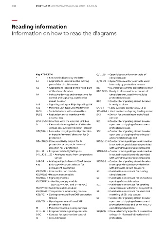
Reading information
Information on how to read the diagrams
Key XT7-XT7M Q/1...25 = Open/close auxiliary contacts of
* = See note indicated by the letter circuit-breaker
A1 = Applications located on the moving Q/26-27 = Open/close auxiliary contacts used
part of the circuit-breaker internally by protection release
A3 = Applications located on the fixed part RC = RC (residual current) protection sensor
of the circuit-breaker RTC EKIP= Ready to close auxiliary contact of
A4 = Indicative devices and connections for circuit-breaker, used internally by
control and signaling, outside the protection release
circuit-breaker RTC = Contact for signaling circuit-breaker
A13 = Signaling unit type Ekip Signalling 10K is ready to close
A15 = Metering unit type Ekip Multimeter S4/1-2 = Early auxiliary contacts (AUE1-2)
BUS1 = Serial interface with external bus S33M/1-2 = Limit contacts of spring loading motor
BUS2 = Redundant serial interface with S43 = Switch for presetting remote/local
external bus control
LINK BUS = Interface with the external Link bus S51 = Contact for signaling circuit breaker
D = Electronic time-lag device of YU under open due to tripping of overcurrent
voltage coil, outside the circuit- breaker protection release
GZi(DBi) = Zone selectivity input for G protection S52 = Contact for signaling circuit breaker
or input in "reverse" direction for D open due to tripping of opening coil
protection and of undervoltage coil
GZo(DBo)= Zone selectivity output for G S75E/1-2 = Contacts for signaling circuit-breaker
protection or output in "reverse" in racked-out position (only provided
direction for D protection with withdrawable circuit-breakers)
| 11...32 = Programmable digital inputs S75l/1-2-5 = Contacts for signaling circuit-breaker
| 41...43 51...53 = Analogue inputs from temperature in racked-in position (only provided
sensor with withdrawable circuit-breakers)
| 44-54 = Analogue inputs from 4-20mA sensor S75T/1-2 = Contact for signaling circuit-breaker
K51 = Ekip type electronic release for in test position (only provided with
overcurrent protection withdrawable circuit-breakers)
K51/COM = Communication module SC = Pushbutton or contact for closing
K51/MEAS =Measurement module circuit-breaker
K51/SIGN = Signaling module S0 = Pushbutton or contact for immediate
K51/SUPPLY = Auxiliary supply module opening of circuit-breaker
(110-220VAC/DC and 24-48VDC) S01 = Pushbutton or contact for opening
K51/SYNC = Synchronization module circuit-breaker with time-delayed trip
K51/TEMP = Temperature monitoring module SR = Pushbutton or contact for electrical
K51/YC = Closing command from EKIP protection resetting of S51 trip contact
release SY = Contact for signaling circuit breaker
K51/YO = Opening command from EKIP open due to tripping of overcurrent
protection release protection release and of Y0, Y02, YU
M = Motor for loading closing springs coils (tripped position)
O 11...32 = Programmable signaling contacts SZi(DFi) = Zone selectivity input for S protection
0 SC = Contact for synchronism control or input in "forward" direction for S
Q = Circuit-breaker protection