
Page 337 - SACE Tmax XT - Technical Catalogue
P. 337
WIRING DIAGR AMS 3/7
03
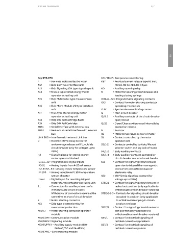
Key XT5-XT6 K51/TEMP= Temperature monitoring
* = See note indicated by the letter K87 = Residual current release type RC Inst,
A12 = Ekip Com type Interface unit RC Sel, RC Sel 200, RC B Type
A13 = Ekip Signaling 10K type signaling unit KO = Auxiliary opening relay
A14 = MOE-E type stored energy motor M = Motor for opening circuit-breaker and
operator actuating unit loading closing springs
A15 = Ekip Multimeter type measurement 0 01-11...32 = Programmable signaling contacts
unit OCI = Contact for motor starting contactor
A16 = Ekip Micro Module I/O type interface operating mechanism
unit O SC = Synchronism monitoring contact
A17 = MOE type stored energy motor Q = Main circuit-breaker
operator actuating unit Q/0..7 = Auxiliary contacts of the circuit-breaker
A18 = Ekip DIN Rail Cartridge Basic open/closed
A19 = Ekip DIN Rail Cartridge Q/26 = Open/Close auxiliary used internally by
BUS1 = Serial interface with external bus protection release
BUS2 = Redundant serial interface with external R = Resistor
bus R2 = Pt100 temperature sensor of motor
LINK BUS = Interface with external Link bus S1 = Contact controlled by the motor
D = Electronic time delay device for operator cam
undervoltage release coilYU, outside S3/1-2 = Contacts controlled by Auto/Manual
circuit-breaker (only for voltages up to selector switch and key lock of motor
250V) S4/1-2 = Early auxiliary contacts
H2 = Signaling lamp for stored energy S4/1-4 = Early auxiliary contacts operated by
motor operator blocked circuit-breaker mounted crank handle
I 01-11...32= Programmable digital inputs S51 = Contact for signaling circuit-breaker
I 41-51 = Analog inputs from 4-20mA sensor open due to tripped thermomagnetic
I 42-44 52...54 = Analog inputs temperature sensor overcurrent protection release or
I Pt 100 = Analog input from Pt 100 temperature electronic relay
sensor of motor S52 = YU/YO trip signaling contact (for
I reset = Digital input for resetting tripped voltage up to 250V)
motor startin contactor operating unit S75E/1 = Contact for signaling circuit-breaker in
J... = Connectors for auxiliary circuits of a racked out position (only applicable to
withdrawable circuit-breaker. withdrawable circuit-breaker versions)
Withdrawal of connectors occurs at the S75E/1-2-3 = Contacts for signaling circuit-breaker
same time as that of circuit-breaker in racked-in position (only applicable
K = Motor starting contactor to withdrawable or plug-in circuit-
K51 = Ekip type electronic relay for breaker versions)
overcurrent protection S75T/1 = Contact for signaling circuit-breaker in
K51/CI = Motor starting contactor operator test position (only applicable to
module withdrawable circuit-breaker versions)
K51/COM = Communication module S87/1 = Contact for electrical signaling of
K51/SIGN = Signaling module residual current relay prealarm
K51/SUPPLY = Auxiliary supply module (110- S87/2 = Contact for electrical signaling of
240VAC/DC and 24-48Vdc) residual current relay alarm
K51/SYNC = Synchronizing module