
Page 397 - SACE Tmax XT - Technical Catalogue
P. 397
WIRING DIAGR AMS 3/67
03
95 35 R1 V3 Vn Ge Szi Ne- 45 D1 C1 C11 11 21 31 41
96 36 U1 R2 V2 Rct Ge- Szo Ne W3 K1 46 C3 C13 12 22 32 42
98 38 U2 V1 Gzo Szc Gzi Rca W4 K2 48 D2 C2 C12 14 24 34 44
YU
S51 S33 M YR Trip Unit I/O EKIP Supply Module Module Module RTC YO2 YC YO Q1 Q2 Q3 Q4
95 35 R1 V3 Vn Ge Szi Ne- 45 D1 C1 C11 11 21 31 41
96 36 U1 R2 V2 Rct Ge- Szo Ne W3 K1 46 C3 C13 12 22 32 42
98 38 U2 V1 Gzo Szc Gzi Rca W4 K2 48 D2 C2 C12 14 24 34 44
YU
S51 S33 M YR Trip Unit I/O EKIP Supply Module Module Module RTC YO2 YC YO Q1 Q2 Q3 Q4
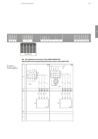
24) RC residual current sensor input (ANSI 64&50N TD)
24a) RC differential ground fault protection sensor input (ANSI 87N)
—
24 - 24a as an
alternative to each
other and to figure 25