
Page 398 - SACE Tmax XT - Technical Catalogue
P. 398
3/68 SACE TMAX XT LOW VOLTAGE MOLDED CASE CIRCUIT-BREAKERS
—
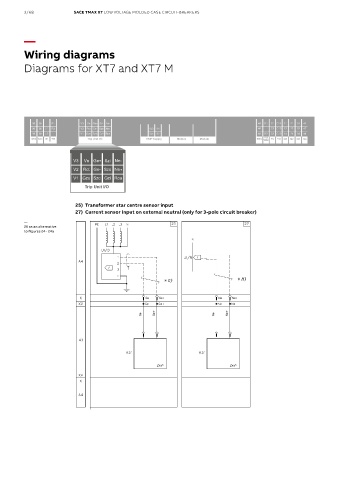
Wiring diagrams
Diagrams for XT7 and XT7 M
95 35 R1 V3 Vn Ge Szi Ne- 45 D1 C1 C11 11 21 31 41
96 36 U1 R2 V2 Rct Ge- Szo Ne W3 K1 46 C3 C13 12 22 32 42
98 38 U2 V1 Gzo Szc Gzi Rca W4 K2 48 D2 C2 C12 14 24 34 44
YU
S51 S33 M YR Trip Unit I/O EKIP Supply Module Module Module RTC YO2 YC YO Q1 Q2 Q3 Q4
95 35 R1 V3 Vn Ge Szi Ne- 45 D1 C1 C11 11 21 31 41
96 36 U1 R2 V2 Rct Ge- Szo Ne W3 K1 46 C3 C13 12 22 32 42
98 38 U2 V1 Gzo Szc Gzi Rca W4 K2 48 D2 C2 C12 14 24 34 44
YU
S51 S33 M YR Trip Unit I/O EKIP Supply Module Module Module RTC YO2 YC YO Q1 Q2 Q3 Q4
25) Transformer star centre sensor input
27) Current sensor input on external neutral (only for 3-pole circuit breaker)
—
25 as an alternative
to figures 24 - 24a