
Page 27 - Reliable_System_Solutions
P. 27
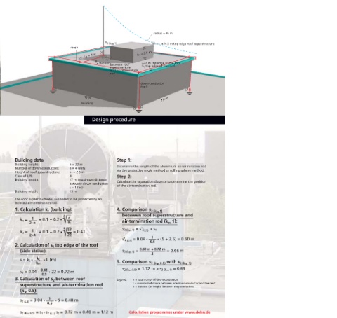
radius = 45 m

                                                         S
                                                         3 (k m  1)                   +24.5 m top edge roof superstructure
                                      mesh
                                              L = 5 m                    h = 2.5 m
                                                                          1
                                              1
                                                    S
                                                    2 (k m  0.5)            +22 m top edge of the roof
                                                           between roof     S top edge of the roof
                                                           superstructure    1
                                                           and air-termination
                                                           rod
                                                                           down-conductor
                                                                           n = 4


                                                                                      15 m
                                              17 m
                                            building


                                                  Design procedure
 Isolated air-termination systems for protecting roof

 superstructures in consideration of standards concerning
 the observance of separation distances


 According to the state of the art of lightning protection systems,  Building data  Step 1:
 large roof superstructures should be protected by isolated air-  Building height:   h = 22 m
 termination systems in case of direct lightning strokes. Electrical  Number of down-conductors:   n = 4 units  Determine the length of the aluminium air-termination rod
 isolation of the lightning protection system from conductive  !  Height of roof superstructure:  h 1  = 2.5 m  via the protective angle method or rolling sphere method.
 parts of the building construction (metal construction parts,  Class of LPS:  III  Step 2:
 reinforcement, etc.) and isolation from electrical conductors in  Building length:  17 m (maximum distance
 the building prevent lightning currents from flowing through  between down-conductors  Calculate the separation distance to determine the position
 control and supply lines as well as interference / destruction of  c = 17 m)  of the air-termination rod.
 sensitive electrical and electronic installations.  Building width:  15 m

 In accordance with the current DIN EN 62305-3 standard, air-  The roof superstructure is supposed to be protected by an
 termination rods and/or elevated air-termination systems (ring  Roof superstructure directly connected to the air-termination system!!!  isolated air-termination rod.
 conductors or spanned cables) should be installed taking the
 calculated separation distance into account in order to protect  1. Calculation k c (building):  4. Comparison s 3 (k m  1)
 roof superstructures on buildings against lightning strokes.     between roof superstructure and
 Three methods can be used for the determining the arrangement  k c =   1  3  c
 and position of air-termination systems:  !  2 • n   + 0.1 + 0.2 •   h  air-termination rod (k 1):
                                                                                          m
 – Rolling sphere method  1        3  17                          s 3 (k m  1) = s’ 2 (L1)   + s 1
 – Protective angle method  k c =   2 • 4   + 0.1 + 0.2 •   22   = 0.41
 – Mesh method.                                                                  1
                                                                  s’ 2  (L1)  = 0.04 •    • (5 + 2.5) = 0.60 m
                                                                                0.5
 The mesh size, the radius of the rolling sphere and the protective  2. Calculation of s top edge of the roof
                             1
 angle depend on the class of LPS. The rolling sphere method as  (side strike):  s 3 (k m  1) =  0.60 m + 0.72 m   = 0.66 m
 universal design method should be used particularly for  is not maintained!!!   2
 geometrically complicated applications. A risk analysis in
 accordance with DIN EN 62305-2 has to be carried out to  s = k i   •   k c   • L (m)    with s
                                                               5. Comparison s 2  (k m  0.5)    3 (k m  1)
 determine the class of LPS. When using the protective angle  k m
 method, the protective angle of an air-termination system        s 2 (k m  0.5) = 1.12 m > s 3 (k m  1) = 0.66
 depends on the selected class of LPS of the lightning protection  s 1 = 0.04 •  0.41  • 22 = 0.72 m
 system and the height of the air-termination system above the  0.5
 area to be protected.  3. Calculation of s  between roof      Legend:  n = total numer of down-conductors
                             2
            superstructure and air-termination rod                     c = maximum distance between one down-conductor and the next
                                                                       h = distance (or height) between ring conductors.
           (k  0.5):
              m
 ok                        1
            s 2  (L1)  = 0.04 •    • 5 = 0.40 m
 is maintained!!!         0.5
                               s
            s 2 (k m  0.5) = s 1   s 2  (L1)   2  = 0.72 m + 0.40 m = 1.12 m  Calculation programmes under www.dehn.de
                        +