
Page 282 - 35_DS702_E_2014_Lightning_Protection_Guide
P. 282
3
distribution board
M of the CHP
3 3 3 3 3 4 3 4
generating plant G M
3
M 3
consumer 3 3 3 3 3 4 3 4 3
installation
3 5
20 kV; 3 ~ 50 Hz ≤125 A
No. Surge protective device Part No. Notes
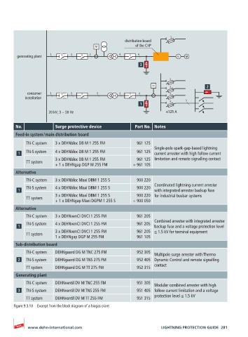
Feed-in system / main distribution board
TN-C system 3 x DEHNbloc DB M 1 255 FM 961 125
Single-pole spark-gap-based lightning
TN-S system 4 x DEHNbloc DB M 1 255 FM 961 125 current arrester with high follow current
3 x DEHNbloc DB M 1 255 FM 961 125 limitation and remote signalling contact
TT system
+ 1 x DEHNgap DGP M 255 FM + 961 105
Alternative
TN-C system 3 x DEHNbloc Maxi DBM 1 255 S 900 220
Coordinated lightning current arrester
TN-S system 4 x DEHNbloc Maxi DBM 1 255 S 900 220
with integrated arrester backup fuse
3 x DEHNbloc Maxi DBM 1 255 S 900 220 for industrial busbar systems
TT system
+ 1 x DEHNgap Maxi DGPM 1 255 S + 900 050
Alternative
TN-C system 3 x DEHNvenCI DVCI 1 255 FM 961 205
Combined arrester with integrated arrester
TN-S system 4 x DEHNvenCI DVCI 1 255 FM 961 205
backup fuse and a voltage protection level
3 x DEHNvenCI DVCI 1 255 FM 961 205 ≤ 1.5 kV for terminal equipment
TT system
1 x DEHNgap DGP M 255 FM 961 105
Sub-distribution board
TN-C system DEHNguard DG M TNC 275 FM 952 305
Multipole surge arrester with Thermo
TN-S system DEHNguard DG M TNS 275 FM 952 405 Dynamic Control and remote signalling
TT system DEHNguard DG M TT 275 FM 952 315 contact
Generating plant
TN-C system DEHNventil DV M TNC 255 FM 951 305
Modular combined arrester with high
TN-S system DEHNventil DV M TNS 255 FM 951 405 follow current limitation and a voltage
TT system DEHNventil DV M TT 255 FM 951 315 protection level ≤ 1.5 kV
Figure 9.3.10 Excerpt from the block diagram of a biogas plant
www.dehn-international.com LIGHTNING PROTECTION GUIDE 281