
Page 307 - 35_DS702_E_2014_Lightning_Protection_Guide
P. 307
protective angle
s
MEB MEB
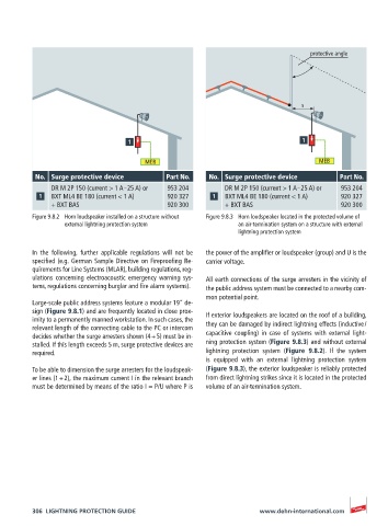
No. Surge protective device Part No. No. Surge protective device Part No.
DR M 2P 150 (current > 1 A – 25 A) or 953 204 DR M 2P 150 (current > 1 A – 25 A) or 953 204
BXT ML4 BE 180 (current < 1 A) 920 327 BXT ML4 BE 180 (current < 1 A) 920 327
+ BXT BAS 920 300 + BXT BAS 920 300
Figure 9.8.2 Horn loudspeaker installed on a structure without Figure 9.8.3 Horn loudspeaker located in the protected volume of
external lightning protection system an air-termination system on a structure with external
lightning protection system
In the following, further applicable regulations will not be the power of the amplifier or loudspeaker (group) and U is the
specified (e.g. German Sample Directive on Fireproofing Re- carrier voltage.
quirements for Line Systems (MLAR), building regulations, reg-
ulations concerning electroacoustic emergency warning sys- All earth connections of the surge arresters in the vicinity of
tems, regulations concerning burglar and fire alarm systems). the public address system must be connected to a nearby com-
mon potential point.
Large-scale public address systems feature a modular 19” de-
sign (Figure 9.8.1) and are frequently located in close prox- If exterior loudspeakers are located on the roof of a building,
imity to a permanently manned workstation. In such cases, the they can be damaged by indirect lightning effects (inductive /
relevant length of the connecting cable to the PC or intercom
decides whether the surge arresters shown (4 + 5) must be in- capacitive coupling) in case of systems with external light-
stalled. If this length exceeds 5 m, surge protective devices are ning protection system (Figure 9.8.3) and without external
required. lightning protection system (Figure 9.8.2). If the system
is equipped with an external lightning protection system
To be able to dimension the surge arresters for the loudspeak- (Figure 9.8.3), the exterior loudspeaker is reliably protected
er lines (1 + 2), the maximum current I in the relevant branch from direct lightning strikes since it is located in the protected
must be determined by means of the ratio I = P/U where P is volume of an air-termination system.
306 LIGHTNING PROTECTION GUIDE www.dehn-international.com