
Page 321 - 35_DS702_E_2014_Lightning_Protection_Guide
P. 321
¨ Are there potential sources of electromagnetic interfer- ¨ Shielded data cables and power lines should use the
ence such as radio-relay systems, mobile phone base sta- same riser duct in the building backbone area. Separate
tions, assembly lines or elevators? riser ducts opposed to one another must be avoided. A
¨ What about the quality of the electrical energy (e.g. distance of 20 cm between these two different types of
harmonics, flickers, voltage drops, excess voltages, tran- cables should not be exceeded.
sients)? ¨ The power lines for the devices and the relevant data lines
¨ What about the risk of a lightning strike (e.g. frequency)? must be basically routed via the same cable route. Sepa-
¨ Is there possible emission? rating webs should be provided. In the horizontal area, it
is advisable to keep a distance of max. 10 cm between
To ensure the performance of data networks even in case these lines.
of the increased requirements to be expected in the future, ¨ If a lightning protection system is installed on the build-
special attention has to be given to the electromagnetic com- ing, the safety distances between the power / data lines
patibility of the installation. Therefore, the design of a data and elements of the external lightning protection system
network should include an earthing and equipotential bond- (air-termination systems, down conductors) must be kept
ing concept which provides information on:
and power / data lines must not be routed in parallel with
¨ Cable duct and cable routing
¨ Cable structure
¨ Active components
¨ Lightning protection
¨ Shielding of signal lines
¨ Equipotential bonding
¨ Surge protection
The most important measures to ensure EMC and thus undis-
turbed data transmission are:
direct earthing
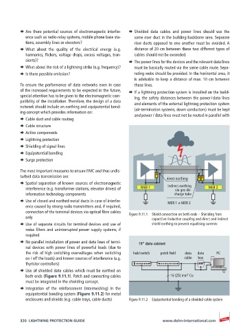
¨ Spatial separation of known sources of electromagnetic
interference (e.g. transformer stations, elevator drives) of MEB 1 indirect earthing MEB 2
via gas dis-
information technology components charge tube
¨ Use of closed and earthed metal ducts in case of interfer- MEB 1 ≠ MEB 2
ence caused by strong radio transmitters and, if required,
connection of the terminal devices via optical fibre cables Figure 9.11.1 Shield connection on both ends – Shielding from
only capacitive / inductive coupling and direct and indirect
¨ Use of separate circuits for terminal devices and use of shield earthing to prevent equalising currents
noise filters and uninterrupted power supply systems, if
required
¨ No parallel installation of power and data lines of termi- 19” data cabinet
nal devices with power lines of powerful loads (due to
the risk of high switching overvoltages when switching hub / switch patch field data data PC
on / off the loads) and known sources of interference (e.g. cable box
thyristor controllers)
¨ Use of shielded data cables which must be earthed on
2
both ends (Figure 9.11.1). Patch and connecting cables 16 (25) mm Cu
must be integrated in the shielding concept.
¨ Integration of the reinforcement (intermeshing) in the
equipotential bonding system (Figure 9.11.2) for metal
enclosures and shields (e.g. cable trays, cable ducts) Figure 9.11.2 Equipotential bonding of a shielded cable system
320 LIGHTNING PROTECTION GUIDE www.dehn-international.com