
Page 427 - ABB_Motor _Protection_and_Control_catalogue_20221216
P. 427
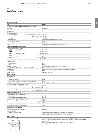
ABB  MOTOR PROTECTION AND CONTROL                                                3/351

          —

          Interface relays


          Technical data                                                                                              03
          Type                                       RA5-1
          Utilization characteristics according to IEC
          Standards                                  IEC 60255-5
          Rated insulation voltage Ui acc. to IEC 60947-4-1  250 V AC
          Pollution degree                           3
          Ambient air temperature
            In free air operation  at Uc = 24 V DC (between E1 and E2) -25…+70 °C
                                        from 0.85 to 1.1 x Uc -25…+55 °C
            Storage                                  -40…+70 °C
          Climatic withstand                         Complies with that of associated contactors
          Maximum operating altitude                 3000 m
          Mounting positions                         No limitation
          Fixing                                     Using the contactor A1 and A2 teminal connecting parts
          Connecting characteristics
          Connection capacity (min. ... max.)
                    Rigid Solid/Stranded          1 x 1...4 mm²
                                                  2 x 1...4 mm²
                    Flexible with ferrule         1 x 0.75...2.5 mm²
                                                  2 x 0.75...2.5 mm²
                    Lugs                          L < 8 mm
                 l  L
                                                  l > 3.5 mm
          Stripping length (all terminals)           10 mm
          Tightening torque
            Recommended                              1 Nm
            Max.                                     1.2 Nm
          Degree of protection                       Protection against direct contact in acc. with EN 50274
          acc. to IEC 60947-1 / EN 60947-1 and IEC 60529 / EN 60529  RA5-1 wired and mounted on the associated contactor
          Screw terminals                            Delivered in open position, screws of unused terminals must be tightened
            All terminals                            M3.5
          Screwdriver type                           Flat Ø 5.5 / Pozidriv 2
          Working data
          Surge suppression
            For contactor coil                       Varistor
            For interface relay coil                 Diode
          Protection against polarity reversal between terminals E1 and E2  Diode
          Interface relay operating time             Closing and drop-out ≤ 10 ms
          Total operating time, interface relay + contactor
            Between energization and:   N.O. contact closing 20…37 ms
                                        N.C. contact opening 17…32 ms
            Between de-energization and:  N.O. contact opening 17…25 ms
                                         N.C. contact closing 20…28 ms
          Electrical input data
          Control voltage (E1 and E2 terminals) Uc
            Rated value                              24 V DC
            Max. range at ambient temperature 20 °C  19…30 V DC
          Max. consumption for Uc = 24 V DC, θ = 20 °C  0.3 W
          "0" status (relay open)               for Uc ≤ 2.4 V DC
                                                 for Ic < 1 mA
          "1" status (relay closed)             for Uc ≥ 19 V DC
          Max. short supply interruption immunity time  2 ms
          Electrical output data
          Switching voltage (A0 and A2 terminals)    ≤ 250 V AC
          Electrical durability
            Number of operating cycles               2 millions (600 cycles/h) on UA16(RA) ... UA75(RA), GA75 contactors
                                                     0.5 million (600 cycles/h) on UA95(RA) and UA110(RA) contactors
          Connection
                                                     The "E1+" and "E2-" input terminals must be connected, according to their polarity, to the PLC output.
                      PLC
                      Output
                U c     –  +                         The RA5-1 is equipped with two terminal pads for connection to the A1 and the A2 terminals of the
               ≤ 250 V AC  24 V DC
                                                     contactor coil.
             A0  A2  E2 –  E1 +
                                                     This coil is supplied between the A0 and the A2 terminals of the RA 5-1.
          RA 5-1
                                                     Mounting: terminals pads clamped inside the contactor coil terminals.
             A1
              KM1
             A2            E0742DG