
Page 710 - ABB_Motor _Protection_and_Control_catalogue_20221216
P. 710
5/60 ABB MOTOR PROTECTION AND CONTROL
—
AS09..S ... AS16..S and
ASL09..S ... ASL16..S 3-pole contactors - with spring terminals
Technical data
Magnet system characteristics for AS09..S … AS16..S contactors
Contactor types AC operated AS09..S AS12..S AS16..S
Coil operating limits AC supply
acc. to IEC 60947-4-1 0.85...1.1 x Uc (at θ ≤ 60 °C); Uc (at θ ≤ 70 °C)
AC control voltage Rated control circuit voltage Uc at 50 Hz 24...415 V
at 60 Hz 24...415 V
Coil consumption Average pull-in value 50 Hz 33 VA
60 Hz 33 VA
50/60 Hz 33 VA
Average holding value 50 Hz 6.5 VA / 1.5 W
60 Hz 5 VA / 1.2 W
50/60 Hz 6.5 VA / 1.5 W
05
Drop-out voltage Approx. 30...50 % of Uc
Operating time
Between coil energization and: N.O. contact closing 9...24 ms
N.C. contact opening 6...18 ms
Between coil de-energization and: N.O. contact opening (1) 5...19 ms
N.C. contact closing (1) 7...22 ms
(1) The use of RC5-1 surge suppressor increases opening time by a factor of 2 to 3.
Magnet system characteristics for ASL09..S … ASL16..S contactors
Contactor types DC operated ASL09..S ASL12..S ASL16..S
Coil operating limits DC supply
acc. to IEC 60947-4-1 0.85...1.1 x Uc (at θ ≤ 60 °C); Uc (at θ ≤ 70 °C)
DC control voltage Rated control circuit voltage Uc 12...240 V DC
Coil consumption Average pull-in value 3 W
Average holding value 3 W
Drop-out voltage Approx. 10...40 % of Uc
Coil time constant Open L/R 12 ms
Closed L/R 40 ms
Operating time
Between coil energization and: N.O. contact closing 36...59 ms
N.C. contact opening 31...53 ms
Between coil de-energization and: N.O. contact opening (1) 13...17 ms
N.C. contact closing (1) 15...20 ms
(1) The use of RT5 surge suppressor increases opening time by a factor of 1.1 to 1.2
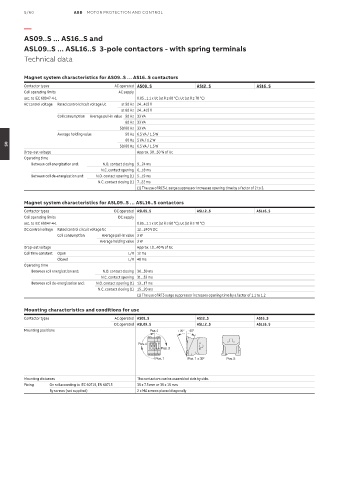
Mounting characteristics and conditions for use
Contactor types AC operated AS09..S AS12..S AS16..S
DC operated ASL09..S ASL12..S ASL16..S
Mounting positions Pos. 2 +30° -30°
Pos. 4
Pos. 3
Pos. 1 Pos. 1 ± 30° Pos. 5
Mounting distances The contactors can be assembled side by side.
Fixing On rail according to IEC 60715, EN 60715 35 x 7.5 mm or 35 x 15 mm
By screws (not supplied) 2 x M4 screws placed diagonally