
Page 993 - ABB_Motor _Protection_and_Control_catalogue_20221216
P. 993
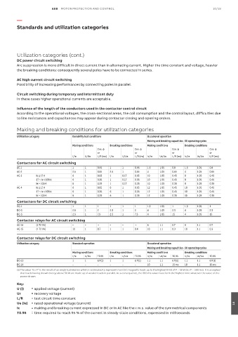
ABB  MOTOR PROTECTION AND CONTROL                                                10/19

          —

          Standards and utilization categories


          Utilization categories (cont.)
          DC power circuit switching
          Arc suppression is more difficult in direct current than in alternating current. Higher the time constant and voltage, heavier
          the breaking conditions: consequently several poles have to be connected in series.

          AC high current circuit switching
          Possibility of increasing performances by connecting poles in parallel.

          Circuit switching during temporary and intermittent duty
          In these cases higher operational currents are acceptable.

          Influence of the length of the conductors used in the contactor control circuit
          According to the operational voltages, the cross-sectional areas, the coil consumption and the control layout, difficulties due
          to line resistances and capacitances may appear during contactor closing and opening orders.


          Making and breaking conditions for utilization categories
          Utilization category       Durability test conditions            Occasional operation
                                                                           Making and breaking capacities - 50 operating cycles
                                     Making conditions  Breaking conditions  Making conditions  Breaking conditions
                                                  Cos. φ            Cos. φ             Cos. φ             Cos. φ
                                                  or                or                 or                 or
                                     I/Ie   U/Ue  L/R (ms)  I/Ie  U/Ue  L/R (ms)  Ic/Ie  Ur/Ue  L/R (ms)  Ic/Ie  Ur/Ue  L/R (ms)
          Contactors for AC circuit switching
          AC-1                       1      1     0.95  1     1     0.95   1.5   1.05  0.8   1.5    1.05  0.8
          AC-2                       2.5    1     0.65  2.5   1     0.65   4     1.05  0.65  4      1.05  0.65
          AC-3     Ie ≤ 17 A         6      1     0.65  1     0.17  0.65   10    1.05  0.45  8      1.05  0.45
                   17 < Ie ≤ 100 A   6      1     0.35  1     0.17  0.35   10    1.05  0.45  8      1.05  0.45
                   Ie > 100 A        6      1     0.35  1     0.17  0.35   10    1.05  0.35  8      1.05  0.35
          AC-4     Ie ≤ 17 A         6      1     0.65  6     1     0.65   12    1.05  0.45  10     1.05  0.45
                   17 < Ie ≤ 100 A   6      1     0.35  6     1     0.35   12    1.05  0.45  10     1.05  0.45
                   Ie > 100 A        6      1     0.35  6     1     0.35   12    1.05  0.35  10     1.05  0.35
          Contactors for DC circuit switching
          DC-1                       1      1     1     1     1     1      1.5   1.05  1     1.5    1.05  1
          DC-3                       2.5    1     2     2.5   1     2      4     1.05  2.5   4      1.05  2.5
          DC-5                       2.5    1     7.5   2.5   1     7.5    4     1.05  15    4      1.05  15
          Contactor relays for AC circuit switching
          AC-14    (≤ 72 VA)         –      –      –    –     –      –     6     1.1   0.7   6      1.1   0.7
          AC-15    (> 72 VA)         10     1     0.7   1     1     0.4    10    1.1   0.3   10     1.1   0.3

          Contactor relays for DC circuit switching
          Utilization category       Standard operation                    Occasional operation
                                                                           Making and breaking capacities - 50 operating cycles
                                     Making conditions  Breaking conditions  Making conditions  Breaking conditions
                                     I/Ie   U/Ue  T0.95  I/Ie  U/Ue  T0.95  Ic/Ie  Ur/Ue  T0.95  Ic/Ie  Ur/Ue  T0.95
          DC-13                      1      1     6 P(1)  1   1     6 P(1)  1.1  1.1   6 P(1)  1.1  1.1   6 P(1)
          DC-14                      –      –     –     –     –     –      10    1.1   15 ms  10    1.1   15 ms
          (1)  The value "6 x P" is the result of an empirical relation which is estimated to represent most DC magnetic loads up to the highest limit of P = 50 W (6 x P = 300 ms). It is accepted
           that loads having drawn energy above 50 W are made up of weaker loads in parallel. As a consequence, the 300 ms value must form the highest limit whatever the value of the
           power drawn.
          Key:
          U (I)   = applied voltage (current)
          Ur     = recovery voltage
          L/R    = test circuit time constant
          Ue (Ie)   = rated operational voltage (current)                                                             14
          Ic     =  making and breaking current expressed in DC or in AC like the r.m.s. value of the symmetrical components
          T0.95   =  time required to reach 95 % of the current in steady-state conditions, expressed in milliseconds