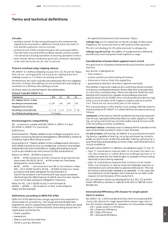
Page 989 - ABB_Motor _Protection_and_Control_catalogue_20221216
P. 989
ABB  MOTOR PROTECTION AND CONTROL                                                10/15

          —

          Terms and technical definitions


          Circuits                                            •  AC operated contactors and contactor relays...
          •  auxiliary circuit: All the conductive parts of a contactor de-  voltage sag: an rms reduction in the AC voltage, at the power
           signed to be inserted in a different circuit from the main cir-  frequency, for durations from a half cycle to a few seconds.
           cuit and the contactor control circuits.           The IEC terminology for this phenomenon is voltage dip.
          •  control circuit: All the conductive parts of a contactor (other
           than the main circuit and the auxiliary circuit) used to control   voltage sag immunity: the ability of equipment to withstand
                                                              momentary electrical power interruptions or sags.
           the contactor's closing operation or opening operation or both.
          •  main circuit: All the conductive parts of a contactor designed
           to be inserted in the circuit that it controls.    Coordination of protections against short circuit
                                                              The goal here is to protect electromechanical starters and soft-
          Thermal overload relay tripping classes             starters.
          IEC 60947-4-1 defines tripping classes 10 A, 10, 20 and 30. Types   Any starter is designed to:
          10 A, 10, etc. correspond to the maximum tripping time for a   •  start motors,
          making current at 7.2 times the setting current.    •  ensure continuous functioning of motors,
          Furthermore, for each class the standard specifies the tripping   •  disconnect motors from the supply line,
          time for 1.5 times the setting current and sets the non tripping   •  guarantee protection of motors against overloads.
          condition at 1.05 times the setting current.        The starter is typically made up of a switching device (contac-
          All these data are summarized in the table below.   tor) and an overload protection device (thermal overload relay
          Extract from IEC 60947-4-1:                         or electronic overload relay). These two devices MUST be coor-
                                                              dinated with equipment capable of providing protection
          Tripping class              10 A  10   20   30      against short circuit (SCPD: short circuit protective device): typ-
          Max. tripping time for 1.5 times                    ically a circuit breaker with magnetic release only or a switch
          the setting current (warm state)  s 120  240  480  720  fuse. These are not necessarily part of the starter.
          Tripping time for 7.2 times                         The characteristics of the starter must comply with the interna-
          the setting current (cold state)  s 2 - 10  4 - 10  6 - 20  9 - 30  tional standard IEC 60947-4-1 which defines the above items as
          For 1.05 times the setting current  No tripping     follows:
                                                              contactor: a mechanical switching device having only one posi-
                                                              tion of rest, operated otherwise than by hand, capable of mak-
          Electromagnetic compatibility                       ing, carrying and breaking currents under normal circuit condi-
          AF... contactors comply with IEC 60947-1, 60947-4-1 and    tions including overload conditions.
          EN  60947-1, 60947-4-1 standards.                   overload release: overload relay or release which operates in the
          Definitions:                                        case of overload and also in case of loss of phase.
          Environment A: "Mainly relates to low-voltage non public or in-  circuit-breaker: defined by IEC 60947-2 as a mechanical switch-
          dustrial networks/locations/installations (EN 50082-2 article 4)   ing device, capable of making, carrying and breaking currents
          including highly disturbing sources".               under normal circuit conditions and also making, carrying for a
          Environment B: "Mainly relates to low-voltage public networks   specified time and breaking currents under specified abnormal
          (EN 50082-1 article 5) such as residential, commercial and light   circuit conditions.
          industrial locations/installations. Highly disturbing sources   IEC publication 60947-4-1 defines coordination types "1" and "2":
          such as arc welders are not covered by this environment".  •  Type "1" coordination requires that, in the event of a short-cir-
          Notice for AF09…AF2650 contactors:                   cuit, the contactor or starter does not endanger persons or in-
          •  AF09 … AF38 contactors and NF contactor relays (produced   stallations and will not then be able to operate without being
                                                               repaired or parts being replaced.
           since week 08-2013), AF40 ... AF96 contactors have been
             designed for environment B.                      •  Type "2" coordination requires that, in short-circuit condi-
          •  AF09 … AF38-..-..-12 contactors and NF..E-12 contactor relays   tions, the contactor or starter does not endanger persons or
                                                               installations and will be able to operate afterwards. The risk
           (48...130 V 50/60 Hz-DC), AF116 ... AF2650 contactors: these
           products have been designed for environment A.      of contacts being light welded is acceptable. In this case, the
           Use of this product in environment B may cause unwanted   manufacturer must stipulate the measures to be taken with
                                                               respect to maintenance of the equipment.
           electromagnetic disturbances in which case the user may be
           required to take adequate mitigation measures.     IEC coordination tables are displayed for IE1, IE2, IE3 and IE4
          Note: for 48...130 V 50/60 Hz-DC in environment B,   motor efficiency classes in regards with N/H or NE/HE motor
          AF09Z … AF38Z-..-..-22 contactor or NFZ..E-22 contactor    design use.
          relays can be selected.
                                                              International Efficiency (IE) classes for single speed
          Definitions according to SEMI F47-0706              electric motors
          SEMI F47-0706 defines the voltage sag immunity required for   IEC 60034-30-1:2014 standard defines four International Effi-
          semiconductor processing, metrology and automated test   ciency (IE) classes for single speed three-phase cage rotor in-
          equipment, and on subsystems and components which are used   duction motors designed for operation on sinusoidal voltage:
          in the construction of semiconductor processing equipment in-    - IE4 = Super premium efficiency
          cluding but not limited to:                             - IE3 = Premium efficiency
          •  Power supplies                                       - IE2 = High efficiency                             14
          •  Generators                                           - IE1 = Standard efficiency
          •  Robots and factory interface
          •  Chillers, pumps, blowers

