
Page 678 - Din prodcuts 2020
P. 678
6/46 ELECTRICAL INSTALL ATION SOLUTIONS FOR BUILDINGS 2CHC 420 001 C0201
—
Command and signaling
E290 Latching relays
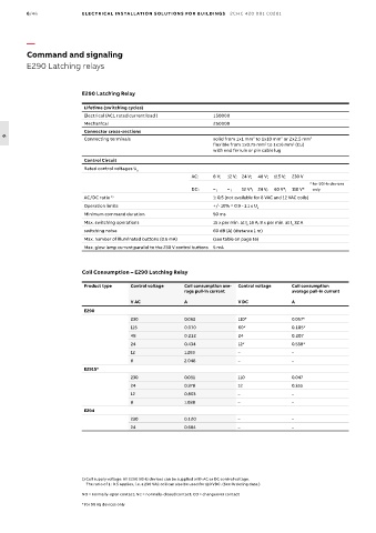
E290 Latching Relay
Lifetime (switching cycles)
Electrical (AC1 rated current load ) 150000
Mechanical 250000
Connector cross-sections
Connecting terminals solid from 1x1 mm to 1x10 mm or 2x2.5 mm 2
2
2
6
flexible from 1x0.75 mm to 1x16 mm (Cu)
2
2
with end ferrule or pin cable lug
Control Circuit
Rated control voltages U
n
AC: 8 V; 12 V; 24 V; 48 V; 115 V; 230 V
* for 50 Hz devices
DC: – ; – ; 12 V*; 24 V; 60 V*; 110 V* only
AC/DC ratio 1) 1: 0.5 (not available for 8 VAC and 12 VAC coils)
Operation limits +/- 10% = 0.9 - 1.1 x U
n
Minimum command duration 50 ms
Max. switching operations 15 x per min. at I 16 A; 8 x per min. at I 32 A
n
n
switching noise 60 dB (A) (distance 1 m)
Max. number of illuminated buttons (0.6 mA) (see table on page 16)
Max. glow lamp current parallel to the 230 V control buttons 5 mA
Coil Consumption – E290 Latching Relay
Product type Control voltage Coil consumption ave- Control voltage Coil consumption
rage pull-in current average pull-in current
V AC A V DC A
E290
230 0.062 110* 0.057*
115 0.070 60* 0.105*
48 0.212 24 0.207
24 0.434 12* 0.558*
12 1.263 – –
8 2.048 – –
E291S*
230 0.051 110 0.047
24 0.378 12 0.355
12 0.803 – –
8 1.088 – –
E294
230 0.120 – –
24 0.684 – –
1) Coil supply voltage: All E290 50Hz devices can be supplied with AC or DC control voltage.
The ratio of 1 : 0.5 applies, i.e. a 230 VAC coil can also be used for 110 VDC. (See Ordering data.)
NO = normally-open contact; NC = normally-closed contact; CO = changeover contact
* for 50 Hz devices only