
Page 679 - Din prodcuts 2020
P. 679
6/47
—
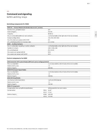
Command and signaling
E290 Latching relays
Switching components for E290
E292-16-… Contact Module (attachable only to 16 A l version)
n
Rated current I per E292 contact 16 A
n
Rated voltage U 250 VAC
n
Frequency 50/60 Hz
6
Max. no. attachable (additional main contacts) 1 unit (attachable on the right side of the main module)
Contact configurations 1CO; 2NO; 1NO+1NC
Max. DC current per contact with 24 VDC 8 A
Min. switching load (for 50 Hz devices only) 24 V; 10 mA
E299-… Auxiliary Contacts
Max. no. attachable (signaling or control contacts) 1 unit (attachable on the right side of the main module)
Number of contacts 1 NO + 1 NC; 2 NO
Min. switching load 24 V, 10 mA
Max. current per contact with AC 5.0 A
Max. current per contact with 24 VDC 5.0 A
Control components for E290
E294 Central On-Off Control Module (different control voltage potential)
Max. no. attachable 1 unit (attachable on the left side of the main module)
Rated current I max. 1 A
n
Rated voltage U 250 VAC
n
E295-PS Permanent Signal Module
Max. no. attachable 1 unit (attachable on the left side of the main module)
Rated current I max. 1 A
n
Rated voltage U 250 VAC
n
E295-GM Group Module
Use of group switching modules 1 unit per defined group
Rated current I max. 1 A
n
Rated voltage U 250 VAC
n
E296-CP Compensator
Compensation when using illuminated buttons Wiring parallel to the main module
Compensation 50 Hz 2.2 uF
60 Hz 2.2 uF
Rated voltage U n 50 Hz 250 VAC
60 Hz 310 VAC
NO = normally-open contact; NC = normally-closed contact; CO = changeover contact