
Page 17 - DIN HV fuse-link
P. 17
Terms and definitions
Rated voltage range
It is important for HV fuse-links that they must be operated
at the voltage for which they have been rated. Accordingly,
the operating voltage corresponds to the maximum rated
voltage of the fuse-link.
Owing to the switching voltage occurring during arcing,
the fuse-link cannot be used at lower voltages without
limitation. A lower operating voltage at which the fuse-link can
still be used without exceeding the system insulation level
during extinction must therefore be taken into account.
From these two values results the permissible voltage range of
the fuse-link, which is shown on the fuse-link or in the technical
data, e.g. 10/24kV.
6kV 3kV / 7,2kV
10kV 6kV / 12kV
15kV 10kV / 17,5kV
20kV 10kV / 24kV
30kV 20kV / 36kV
Breaking capacity I
1
The breaking capacity is also referred to as the “rated
maximum breaking current”. This clearly indicates that this is
the maximum current which can be interrupted by the fuse-link. Time-current characteristic
I of the fuse-link must be greater than the maximum short- (I/t characteristic)
1
circuit current at the site of the fuse-link (I > I ).
1 Kmax
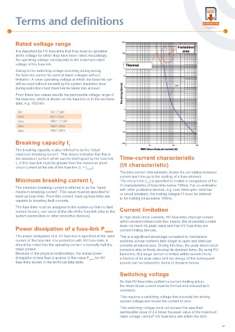
The time-current characteristic shows the correlation between
current and time up to the melting of a fuse-element.
Minimum breaking current I 3 The virtual time (t ) is specifi ed to enable a comparison of the
vs
The minimum breaking current is referred to as the “rated l/t characteristics of fuse-links below 100ms. For co-ordination
minimum breaking current”. This value must be specifi ed for with other protective devices, e.g. load interruptor switches
2
back-up fuse-links. From this current, back-up fuse-links are or circuit breakers, the melting integral I t must be referred
capable to breaking fault currents. to for melting times below 100ms.
The fuse-links must be assigned to the system so that no fault
current below I can occur at the site of the fuse-link (due to the Current limitation
3
system parameters or other protective devices). At high short-circuit currents, HV fuse-links interrupt current
within several milliseconds that means, the sinusoidal current
does not reach its peak value and that HV fuse-links are
Power dissipation of a fuse-link P warm current limiting devices.
The power dissipation of a HV fuse-link is specifi ed at the rated This is a signifi cant advantage compared to mechanical
current of the fuse-link. For protection with HV fuse-links, it switches whose contacts take longer to open and interrupt
should be noted that the operating current is normally half the currents at natural zero. During this time, the peak short-circuit
rated current. current is able to freely develop its dynamic force. By using HV
Because of the physical relationships, the actual power fuse-links, this surge current is limited within several ms to
dissipation is less than a quarter of the value P warm for HV a fraction of its peak value and the design of the subsequent
fuse-links shown in the technical data table. system can be reduced in terms of dynamic forces.
Switching voltage
So that HV fuse-links perform a current-limiting action,
the short-circuit current must be limited and reduced as it
increases.
This requires a switching voltage that exceeds the driving
system voltage and forces the current to zero.
This switching voltage must not exceed the specifi ed
permissible value of 2,2 times the peak value of the maximum
rated voltage. Limitor HV fuse-links are within this limit.
®
17