
Page 268 - 35_DS702_E_2014_Lightning_Protection_Guide
P. 268
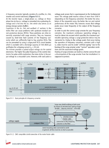
A frequency converter typically consists of a rectifier, d.c. link,   voltage peak occurs that is superimposed on the fundamental
       inverter and control electronics (Figure 9.1.1).  wave. This voltage peak reaches values of more than 1200 V
       At  the  inverter  input,  a  single-phase  a.c.  voltage  or  three-  (depending on the frequency converter). The better the simu-
       phase line-to-line a.c. voltage is converted into a pulsating d.c.   lation of the sinusoidal curve, the better the run and control
       voltage and is fed into the d.c. link which also serves as an   performance of the motor. This, however, means that voltage
       energy storage system (buffer).              peaks occur more frequently at the output of the frequency
       Capacitors in the d.c. link and earthed L-C sections in the   converter.
       mains filter can cause problems with upstream residual cur-  In order to pick the correct surge arrester for your frequency
       rent protective devices (RCDs). These problems are often in-  converter, the maximum continuous operating voltage U c
       correctly associated with surge arresters. They are, however,   must be taken into account which specifies the maximum per-
       caused by short-time fault currents of the frequency con-  missible operating voltage a surge protective device may be
       verter which are sufficiently high to trip sensitive RCDs. This   connected to. Owing to the voltage peaks that occur during
       can be prevented by using a surge-proof RCD circuit breaker   the operation of frequency converters, arresters with a high
       which is available with a discharge capacity of 3 kA (8/20 µs)    U c  value must be used to avoid “artificial ageing” due to the
       and higher for a tripping current I ∆n  = 30 mA.  heating of the surge arrester under “normal” operation condi-
       The inverter provides a pulsed output voltage via the control   tions and the associated voltage peaks.
       electronics. The higher the pulse frequency of the control elec-  Heating of surge arresters can lead to a shorter service life and
       tronics for pulse width modulation, the more similar is the out-  a disconnection of the surge arrester from the installation it is
       put voltage to a sinusoidal curve. However, with each pulse a   supposed to protect.


                INPUT                                                       OUTPUT
                           rectifier      d.c. link          inverter
                                               +                        +            motor
                  L1                                    V1     V3     V5
                                                                               U1
                                                                                      M
                  L2                       C                                   V1     3~
                                                                               W1
                  L3                           –        V4     V6     V2  –


                                           control electronics
          e.g. 4 – 20 mA
                                      control / monitoring / communication
          data


       Figure 9.1.1  Basic principle of a frequency converter

                                                    large-area shield earthing at both ends
                                                    by means of constant force spring of type
                                                    SA KRF… (Part No. 919 031 – 919 038)

                               frequency converter                              motor
                                                            shielded motor
                                                            feeder cable
         voltage supply                               connection of the frequency
                                 compact filter        converter to the filter

                                         metal mounting plate connected to earth
                                         in general: all lines must be as short as possible

       Figure 9.1.2  EMC-compatible shield connection of the motor feeder cable


            www.dehn-international.com                             LIGHTNING PROTECTION GUIDE  267