
Page 269 - 35_DS702_E_2014_Lightning_Protection_Guide
P. 269
M
f1 3~
f2
f1
f2
M
3~
No. Surge protective device Part No.
DEHNguard modular DG M TNS 275 (TN-S system) 952 400
DEHNguard modular DG M TT 275 (TT system) 952 310
DEHNguard S DG S WE 600 (3 items) 952 077
DEHNbloc Maxi DBM 1 760 FM (3 items) 961 175
+ DEHNguard S DG S WE 600 (3 items) + 952 077
BLITZDUCTOR XT BXT ML2 BE S 24 (e.g. 4 – 20 mA) 920 224
+ BLITZDUCTOR XT base part BXT BAS + 920 300
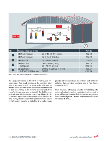
Figure 9.1.3 Frequency converter with drives in LPZ 0 A and LPZ 1
The high pulse frequency at the output of the frequency con- potential differences between the different parts of the in-
verter causes field-based interference. To avoid that other stallation, thus preventing equalising currents from flowing
systems are interfered with, the motor feeder cable must be through the shield.
shielded. The shield of the motor feeder cable must be earthed
on both ends, namely at the frequency converter and at the When integrating a frequency converter in the building auto-
motor. To this end, large-area contact with the shield must be mation, all evaluation and communication interfaces must be
provided, preferably by constant force springs (Figure 9.1.2), protected by surge protective devices to prevent surge-related
to fulfil EMC requirements. Intermeshed earth-termination sys- system failure. Figure 9.1.3 shows an example of the control-
tems, namely the connection of the earth-termination system ler interface 4 – 20 mA.
of the frequency converter to that of the drive motor, reduce
268 LIGHTNING PROTECTION GUIDE www.dehn-international.com