
Page 272 - 35_DS702_E_2014_Lightning_Protection_Guide
P. 272
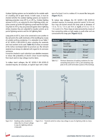
Outdoor lighting systems can be installed at the outside walls   ness of at least 5 cm in a radius of 3 m around the lamp pole
       of a building and in open terrain. In both cases, it must be   (Figure 9.2.1).
       checked whether the outdoor lighting systems are located in
       lightning protection zone LPZ 0 A  or LPZ 0 B  . Outdoor lighting   To reduce step voltages, the IEC  62305-3 (EN 62305-3)
       systems in LPZ 0 A  are subjected to direct lightning strikes, im-  standard requires, for example, potential control. To this end,
       pulse currents up to the full lightning current and the full light-  four rings are buried around the lamp pole at distances of
       ning field. In LPZ 0 B  they are protected against direct lightning   1.0 m; 4.0 m; 7.0 m and 10.0 at depths of 0.5 m; 1.0 m;
       strikes, however, they are subjected to impulse currents up to   1.5 m and 2.0 m. These rings are interconnected by means of
       partial lightning currents and the full lightning field.  four connecting cables at right angles to each other and are
                                                    connected to the lamp pole (Figure 9.2.2).
       Lamp poles in LPZ 0 A  have to be connected to one another in
       the soil and to the earth electrodes of the buildings by means
       of suitable earthing conductors. It is advisable to use Table 7   Material  Configuration  Earthing conductor
       of IEC 62305-3 (EN 62305-3) when selecting the materials
       and cross-sections to be used. Table 9.2.1 shows an excerpt   Copper  Stranded /       50 mm 2
       of the before mentioned table for practical use. The relevant   round / tape
       material must always be selected with regard to its corrosion   Round, galvanised     78 mm 2
       resistance.                                   Steel      Tape, galvanised     90 mm 2
       It must be checked in each individual case whether measures
       to reduce the probability of electric shock hazard resulting   Stainless   Round     78 mm 2
       from touch and / or step voltage must be taken.  steel (V4A)  Tape         100 mm 2
                                                    Table 9.2.1  Minimum dimensions of earthing conductors for inter-
       To reduce touch voltages, the IEC 62305-3 (EN 62305-3)   connecting lamp poles in LPZ 0 A  and connecting lamp
       standard requires, for example, an asphalt layer with a thick-  poles to the earth-termination systems of the buildings


         asphalt layer
         ≥ 5 cm

                                                                  ±0
                                                                    –0.5 m  –1.0 m
                                                                                 –1.5 m
                                                                                         –2.0 m
               3 m        3 m
                                                              1 m
                                                                      4 m
                                                                              7 m
                                                                                      10 m

       Figure 9.2.1  Standing surface insulation to   Figure 9.2.2  Potential control to reduce step voltage in case of a lightning strike to a lamp
               reduce the risk of touch voltage   pole
               in case of a lightning strike to
               a lamp pole


            www.dehn-international.com                             LIGHTNING PROTECTION GUIDE  271