
Page 264 - 35_DS702_E_2014_Lightning_Protection_Guide
P. 264
It is recommended to install telecommunication lines in metal
ducts which are electrically connected and completely en-
closed. The metal cable duct systems should be connected with
low impedance to earth as frequently as possible, at least at
the beginning and at the end (Figure 8.2.5.5).
8.2.6 Protection and availability of installa-
tions thanks to maintenance strategies
As with all electrical and electronic devices, the electronic com-
ponents of surge protective devices for information technol-
ogy systems are subject to ageing. Figure 8.2.6.1 shows the
“bath tub curve”.
Therefore, the aim of a maintenance strategy for SPDs should
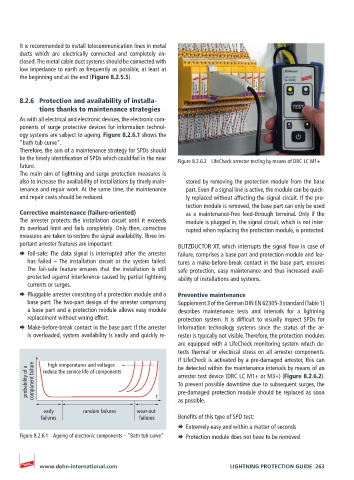
be the timely identification of SPDs which could fail in the near Figure 8.2.6.2 LifeCheck arrester testing by means of DRC LC M1+
future.
The main aim of lightning and surge protection measures is
also to increase the availability of installations by timely main- stored by removing the protection module from the base
tenance and repair work. At the same time, the maintenance part. Even if a signal line is active, the module can be quick-
and repair costs should be reduced. ly replaced without affecting the signal circuit. If the pro-
tection module is removed, the base part can only be used
Corrective maintenance (failure-oriented) as a maintenance-free feed-through terminal. Only if the
The arrester protects the installation circuit until it exceeds module is plugged in, the signal circuit, which is not inter-
its overload limit and fails completely. Only then, corrective rupted when replacing the protection module, is protected.
measures are taken to restore the signal availability. Three im-
portant arrester features are important: BLITZDUCTOR XT, which interrupts the signal flow in case of
¨ Fail-safe: The data signal is interrupted after the arrester failure, comprises a base part and protection module and fea-
has failed – The installation circuit or the system failed. tures a make-before-break contact in the base part, ensures
The fail-safe feature ensures that the installation is still safe protection, easy maintenance and thus increased avail-
protected against interference caused by partial lightning ability of installations and systems.
currents or surges.
¨ Pluggable arrester consisting of a protection module and a Preventive maintenance
base part: The two-part design of the arrester comprising Supplement 3 of the German DIN EN 62305-3 standard (Table 1)
a base part and a protection module allows easy module describes maintenance tests and intervals for a lightning
replacement without wiring effort. protection system. It is difficult to visually inspect SPDs for
¨ Make-before-break contact in the base part: If the arrester information technology systems since the status of the ar-
is overloaded, system availability is easily and quickly re- rester is typically not visible. Therefore, the protection modules
are equipped with a LifeCheck monitoring system which de-
tects thermal or electrical stress on all arrester components.
If LifeCheck is activated by a pre-damaged arrester, this can
high temperatures and voltages
probability of a component failure reduce the service life of components t arrester test device (DRC LC M1+ or M3+) (Figure 8.2.6.2).
be detected within the maintenance intervals by means of an
To prevent possible downtime due to subsequent surges, the
pre-damaged protection module should be replaced as soon
early random failures wear-out as possible.
failures failures Benefits of this type of SPD test:
¨ Extremely easy and within a matter of seconds
Figure 8.2.6.1 Ageing of electronic components – “Bath tub curve” ¨ Protection module does not have to be removed
www.dehn-international.com LIGHTNING PROTECTION GUIDE 263