
Page 314 - 35_DS702_E_2014_Lightning_Protection_Guide
P. 314
Electrical installations in buildings with complex operator con- The KNX bus is supplied with a safety extra-low voltage (SELV)
trol units, displays and control devices are frequently equipped of max. 29 V. The cable length within a line segment and the
with an installation bus system. The EIB (European Installation length of the bus cable between two bus devices are limited.
Bus), which was developed at the beginning of the 1990s, is a In case of a maximum length of 1000 m per line segment, the
widely used installation bus system. Today this installation bus KNX systems may be destroyed by coupling despite of their
system is still the core of a KNX system which is the world’s high dielectric strength.
first open standard described in the European EN 50090 stand-
ard. Moreover, it must be observed that no induction loops are
An advantage of the KNX standard is the interoperability be- formed when installing the cables. Therefore, the bus and low-
tween different devices in all industries independent of the voltage cables leading to the bus devices must be installed
manufacturer. Thus, the values of a wind and rain sensor or close to each other (Figure 9.10.2).
a temperature and sun sensor can be processed in different Loops are also formed if a metal construction or pipe is con-
building systems. Lighting systems can be switched on or off nected to the main earthing busbar (Figure 9.10.3). Also in
as needed depending on the light level and different lighting this case, it is advisable to install the cables as close as pos-
scenarios can be programmed. Consumption values can be re- sible to the construction or pipe.
corded and used for load management. These are only some of
the many applications where KNX systems can be used. In ad- Structure with external lightning protection system
dition to these advantages, the installation time and the costs The standard calls for lightning equipotential bonding, there-
of such systems can be considerably reduced. fore all cables at the zone transition from LPZ 0 A to 1 must be
protected by lightning current arresters. Since the electromag-
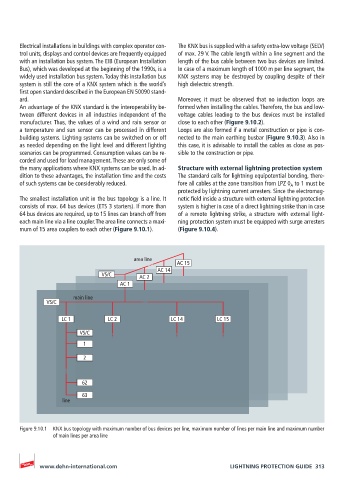
The smallest installation unit in the bus topology is a line. It netic field inside a structure with external lightning protection
consists of max. 64 bus devices (ETS 3 starters). If more than system is higher in case of a direct lightning strike than in case
64 bus devices are required, up to 15 lines can branch off from of a remote lightning strike, a structure with external light-
each main line via a line coupler. The area line connects a maxi- ning protection system must be equipped with surge arresters
mum of 15 area couplers to each other (Figure 9.10.1). (Figure 9.10.4).
area line
AC 15
AC 14
VS/C AC 2
AC 1
main line
VS/C
LC 1 LC 2 LC 14 LC 15
VS/C
1
2
62
63
line
Figure 9.10.1 KNX bus topology with maximum number of bus devices per line, maximum number of lines per main line and maximum number
of main lines per area line
www.dehn-international.com LIGHTNING PROTECTION GUIDE 313