
Page 387 - 35_DS702_E_2014_Lightning_Protection_Guide
P. 387
in parallel with a low-voltage cable. However, a distance of
230 V 10 mm must be kept after removing the J-Y(ST)Y cable sheath.
Loops are also formed if a node is attached to a metallic con-
struction / pipe which is connected to the main earthing bus-
node bar (Figure 9.20.3). Also in this case, it is advisable to route
induction loop MEB the cables as close as possible to the construction / pipe.
Surge protection in case of a combination topology
If the inputs / outputs connected to the node are located in
close proximity to the node, surge protective devices are not
required.
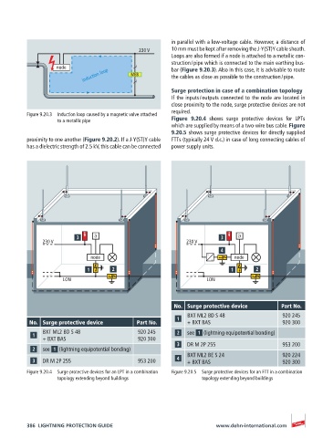
Figure 9.20.3 Induction loop caused by a magnetic valve attached
to a metallic pipe Figure 9.20.4 shows surge protective devices for LPTs
which are supplied by means of a two-wire bus cable. Figure
9.20.5 shows surge protective devices for directly supplied
proximity to one another (Figure 9.20.2). If a J-Y(ST)Y cable FTTs (typically 24 V d.c.) in case of long connecting cables of
has a dielectric strength of 2.5 kV, this cable can be connected power supply units.
ϑ ϑ
230 V 230 V
node node
LON LON
No. Surge protective device Part No.
BXT ML2 BD S 48 920 245
No. Surge protective device Part No. + BXT BAS 920 300
BXT ML2 BD S 48 920 245 see (lightning equipotential bonding)
+ BXT BAS 920 300
DR M 2P 255 953 200
see (lightning equipotential bonding)
BXT ML2 BE S 24 920 224
DR M 2P 255 953 200 + BXT BAS 920 300
Figure 9.20.4 Surge protective devices for an LPT in a combination Figure 9.20.5 Surge protective devices for an FTT in a combination
topology extending beyond buildings topology extending beyond buildings
386 LIGHTNING PROTECTION GUIDE www.dehn-international.com