
Page 386 - 35_DS702_E_2014_Lightning_Protection_Guide
P. 386
Medium Transceiver Transmission Network expansion Node ¨ Node Node supply
Two-wire TP/XF-78 78 kbit/s 1400 m bus / line Separately
Two-wire TP/XF-1250 1250 kbit/s 130 m bus / line Separately
2700 m bus / line J-Y(ST)Y 2x2x0.8
Two-wire FTT10-A 78 kbit/s Separately
500 m open structure 320 m open structure
2200 m bus / line J-Y(ST)Y 2x2x0.8
Two-wire LPT-10 78 kbit/s Via bus cable
500 m open structure 320 m open structure
Table 9.20.1 Transceivers (most common transceivers are printed in bold) with their transmission rates and maximum network expansion
The LonWorks technology allows to implement distributed Transceivers) (LPTs are compatible with FTTs at the same
automation systems. In this context, intelligent nodes com- bus).
®
municate via the LonTalkProtocol . The neuron chip (3120, The transceivers in FTT / LPT networks have the core / core
3150 and various enhancements), which accesses a transmis- and core / earth capacitances shown in Table 9.20.2. If surge
sion medium via a transceiver and features an I/O circuit for protective devices are installed, their capacitances (core / core
connecting, for example switches, relays, analogue outputs, and core / earth) must also be considered since the maximum
analogue value measurement systems, is the core of a node number of transceivers to be used is reduced accordingly
(Figure 9.20.1). (Table 9.20.3).
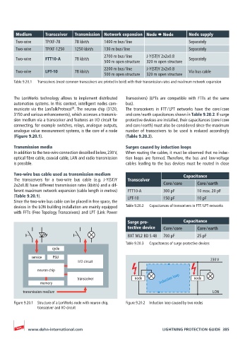
Transmission media Surges caused by induction loops
In addition to the two-wire connection described below, 230 V, When routing the cables, it must be observed that no induc-
optical fibre cable, coaxial cable, LAN and radio transmission tion loops are formed. Therefore, the bus and low-voltage
is possible. cables leading to the bus devices must be routed in close
Two-wire bus cable used as transmission medium Capacitance
The transceivers for a two-wire bus cable (e.g. J-Y(ST)Y Transceiver
2x2x0.8) have different transmission rates (kbit/s) and a dif- Core / core Core / earth
ferent maximum network expansion (cable length in metres) FTT10-A 300 pF 10 max. 20 pF
(Table 9.20.1). LPT-10 150 pF 10 pF
Since the two-wire bus cable can be placed in free space, the
devices in the LON building installation are mainly equipped Table 9.20.2 Capacitances of transceivers in FTT / LPT networks
with FFTs (Free Topology Transceivers) and LPT (Link Power
Surge pro- Capacitance
tective device Core / core Core / earth
BXT ML2 BD S 48 700 pF 25 pF
Table 9.20.3 Capacitances of surge protective devices
cycle
service PSU
I / O circuit 230 V
neuron chip
transceiver node induction loop node
memory
transmission medium LON
Figure 9.20.1 Structure of a LonWorks node with neuron chip, Figure 9.20.2 Induction loop caused by two nodes
transceiver and I/O circuit
www.dehn-international.com LIGHTNING PROTECTION GUIDE 385