
Page 382 - 35_DS702_E_2014_Lightning_Protection_Guide
P. 382
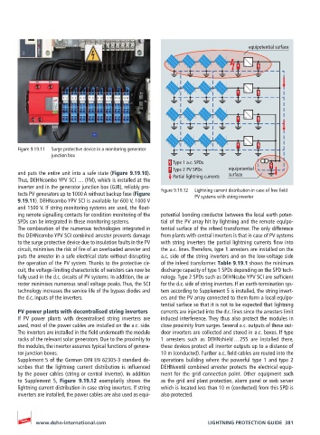
equipotential surface


       Figure 9.19.11   Surge protective device in a monitoring generator
                 junction box
                                                        Type 1 a.c. SPDs
                                                        Type 2 PV SPDs    equipotential
       and puts the entire unit into a safe state (Figure 9.19.10).       surface
       Thus, DEHNcombo YPV SCI … (FM), which is installed at the   Partial lightning currents
       inverter and in the generator junction box (GJB), reliably pro-
       tects PV generators up to 1000 A without backup fuse (Figure   Figure 9.19.12   Lightning current distribution in case of free field
                                                               PV systems with string inverter
       9.19.11). DEHNcombo YPV SCI is available for 600 V, 1000 V
       and 1500 V. If string monitoring systems are used, the float-
       ing remote signalling contacts for condition monitoring of the   potential bonding conductor between the local earth poten-
       SPDs can be integrated in these monitoring systems.  tial of the PV array hit by lightning and the remote equipo-
       The combination of the numerous technologies integrated in   tential surface of the infeed transformer. The only difference
       the DEHNcombo YPV SCI combined arrester prevents damage   from plants with central inverters is that in case of PV systems
       to the surge protective device due to insulation faults in the PV   with string inverters the partial lightning currents flow into
       circuit, minimises the risk of fire of an overloaded arrester and   the a.c. lines. Therefore, type 1 arresters are installed on the
       puts the arrester in a safe electrical state without disrupting   a.c. side of the string inverters and on the low-voltage side
       the operation of the PV system. Thanks to the protective cir-  of the infeed transformer. Table 9.19.1 shows the minimum
       cuit, the voltage-limiting characteristic of varistors can now be   discharge capacity of type 1 SPDs depending on the SPD tech-
       fully used in the d.c. circuits of PV systems. In addition, the ar-  nology. Type 2 SPDs such as DEHNcube YPV SCI are sufficient
       rester minimises numerous small voltage peaks. Thus, the SCI   for the d.c. side of string inverters. If an earth-termination sys-
       technology increases the service life of the bypass diodes and   tem according to Supplement 5 is installed, the string invert-
       the d.c. inputs of the inverters.            ers and the PV array connected to them form a local equipo-
                                                    tential surface so that it is not to be expected that lightning
       PV power plants with decentralised string inverters  currents are injected into the d.c. lines since the arresters limit
       If PV power plants with decentralised string inverters are   induced interference. They thus also protect the modules in
       used, most of the power cables are installed on the a.c. side.   close proximity from surges. Several a.c. outputs of these out-
       The inverters are installed in the field underneath the module   door inverters are collected and stored in a.c. boxes. If type
       racks of the relevant solar generators. Due to the proximity to   1 arresters such as DEHNshield … 255 are installed there,
       the modules, the inverter assumes typical functions of genera-  these devices protect all inverter outputs up to a distance of
       tor junction boxes.                          10 m (conducted). Further a.c. field cables are routed into the
       Supplement 5 of the German DIN EN 62305-3 standard de-  operations building where the powerful type 1 and type 2
       scribes  that  the  lightning  current  distribution  is  influenced   DEHNventil combined arrester protects the electrical equip-
       by the power cables (string or central inverter). In addition   ment for  the grid connection point.  Other  equipment  such
       to Supplement 5,  Figure 9.19.12 exemplarily shows the   as the grid and plant protection, alarm panel or web server
       lightning current distribution in case string inverters. If string   which is located less than 10 m (conducted) from this SPD is
       inverters are installed, the power cables are also used as equi-  also protected.


            www.dehn-international.com                             LIGHTNING PROTECTION GUIDE  381