
Page 435 - 35_DS702_E_2014_Lightning_Protection_Guide
P. 435
While in Figure 9.31.1 it is assumed that a coordinated type 1
lightning current arrester is installed in the power supply
and information technology system of the building, a type 1
SPD is required for the outgoing circuits of the safety light-
ing system since lightning equipotential bonding is required
(Figure 9.31.2). Since these circuits are both supplied dur-
ing a.c. and d.c. operation, the type 1 arrester installed at the
E 30 zone transition from LPZ 0 A to LPZ 1 (entry point to the build-
E 30
ing) must be suitable for this purpose. In this case, standard
spark-gap-based arresters designed and tested for use in a.c.
systems cannot be used due to the lacking zero crossing during
d.c. operation which extinguishes the spark gap. DEHNsecure
M 1 242, which is both designed for d.c. and a.c. operation
(max. backup fuse 10 gl/gG), is ideally suited for this purpose.
transition to the fire compartment
transition to the fire compartment
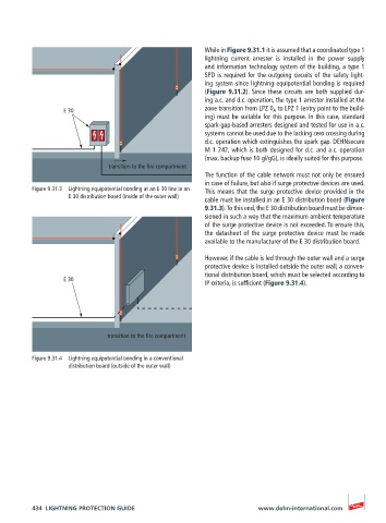
The function of the cable network must not only be ensured
in case of failure, but also if surge protective devices are used.
Figure 9.31.3 Lightning equipotential bonding at an E 30 line in an This means that the surge protective device provided in the
E 30 distribution board (inside of the outer wall)
cable must be installed in an E 30 distribution board (Figure
9.31.3). To this end, the E 30 distribution board must be dimen-
sioned in such a way that the maximum ambient temperature
of the surge protective device is not exceeded. To ensure this,
the datasheet of the surge protective device must be made
available to the manufacturer of the E 30 distribution board.
However, if the cable is led through the outer wall and a surge
protective device is installed outside the outer wall, a conven-
tional distribution board, which must be selected according to
E 30
E 30
IP criteria, is sufficient (Figure 9.31.4).
transition to the fire compartment
transition to the fire compartment
Figure 9.31.4 Lightning equipotential bonding in a conventional
distribution board (outside of the outer wall)
434 LIGHTNING PROTECTION GUIDE www.dehn-international.com