
Page 793 - ABB_Motor _Protection_and_Control_catalogue_20221216
P. 793
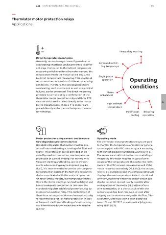
ABB  MOTOR PROTECTION AND CONTROL                                                 7/3

          —

          Thermistor motor protection relays
          Applications


                                                                                       Heavy duty starting

                           Direct temperature monitoring
                           Generally, motor damage caused by overload or   Increased switch-
                           overheating situations can be prevented in differ-  ing  frequencys
                           ent ways. Compared to the indirect temperature
                           measuring which monitors the motor current, the
                           temperature inside the motor can be measured
                           by direct temperature measuring. This enables di-  Single phase    Operating
                           rect control and evaluation of different operating   operation
                           conditions. Therefore, the consequences from                       conditions
                           overheating, such as abrasion as well as electrical
                           failures, can be prevented. The direct measuring   Phase
                           principle is carried out by a combination of the   unbalanced
                           thermistor motor protection relay and three PTC
                           sensors which are installed directly in the motor                                          07
                           by the manufacturer. Those 3 PTC sensors are       High ambient
                           placed directly at the thermal hotspots, the mo-   temperature
                           tor windings.                                                   Insufficient      Breaking

                                                                                               cooling  operation


                           Motor protection using current- and tempera-  Operating mode
                           ture-dependent protective devices           The thermistor motor protection relays are used
                           IEC 60204 stipulates that motors must be pro-  to monitor the temperature of motors or genera-
                           tected from overheating at a rating of 0.5 kW and   tors equipped with PTC sensors type A according
                           higher. The protection can be provided or exe-  to the latest product standard IEC/EN 60947-8.
                           cuted by overload protection, overtemperature   The sensors are built-in into the motor windings,
                           protection or current limiting. For motors with   measuring the motor heating. In case of an in-
                           frequent starting and braking, and in environ-  crease of the temperature in the motor, the resis-
                           ments where cooling may be impaired (e.g. by   tance of the PTC sensors increases as well. If the
                           dust), it is recommended to use the overtempera-  motor heats-up excessively (>2.83 kΩ), the output
                           ture protection option in the form of a protective   relay(s) de-energize(s) and the corresponding LED
                           device coordinated with this mode of operation.   displays the overtemperature. A short circuit and
                           On rotor-critical motors, overtemperature detec-  an interrupted wire within the sensor circuit can
                           tion in the stator windings can lead to delayed and   also be detected. A reset is only possible after
                           hence inadequate protection. In this case, the   cooling down of the motor (<1.1 kΩ) or after a
                           standards stipulate additional protection, e.g. by   wire interruption, or a short circuit within the
                           means of an overload relay. This combination of   sensor circuit has been removed. A reset after
                           thermistor motor protection and an overload relay   tripping can be done manually with the Test / Re-
                           is recommended for full motor protection in case   set button, externally with a push button be-
                           of frequent starting and braking of motors, irreg-  tween S1 and 1T2/2T2, or automatically by jump-
                           ular intermittent duty or excessive switching fre-  ering S1-1T2/2T2.
                           quency.