Page 794 - ABB_Motor _Protection_and_Control_catalogue_20221216
P. 794

7/4              ABB  MOTOR PROTECTION AND CONTROL

          —

          Thermistor motor protection relays
          Operating controls


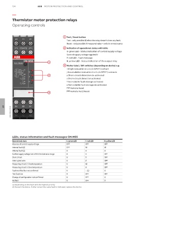
                                             1  Test / Reset button

                                               Test – only possible if/when the relay doesn't show any fault.
                                               Reset – only possible if measured value < switch-on resistance
                                             2  Indication of operational states with LEDs

                                                 U: green LED - Status indication of control supply voltage
                                               Control supply voltage applied V
                                               F: red LED - Fault message
                                  1            R: yellow LED - Status indication of the output relay
                                             3  Marker label / DIP switches (depending on device) e.g.

                                               i Single evaluation 2 x 1 c/o (SPDT) contact
                                               j Accumulative evaluation 1 x 2 c/o (SPDT) contacts
                                  2            y Short-circuit detection de-activated
                                               x Short-circuit detection activated
                                               f Non-volatile fault storage activated
                                               e Non-volatile fault storage de-activated
                                                Reset  Remote Reset
                                               Remote
                                               Test/Reset  Remote Test/Reset
                                               Remote
                                  3


        2CDC 253 001 F0015
   07


          LEDs, status information and fault messages CM-MSS
          Operational state                    U: green LED  F: red LED  R: yellow LED
          Absence of control supply voltage    OFF          OFF          OFF
          Internal fault (2)                   OFF          W            W
          Internal fault (2)                   X            X            X
          Control supply voltage not within the tolerance range  X  V    OFF
          Short circuit                        V            Y            OFF
          Interrupted wire                     V            Z            OFF
          Measuring circuit 2: Overtemperature  V           W            OFF
          Measuring circuit 1: Overtemperature  V           V            OFF
          Fault rectified but not confirmed    V            -- (1)       X
          Test function                        X            OFF          OFF
          Change of configuration not confirmed   V         OFF          X
          No fault                             V            OFF          V
          (1) Depending on the fault with the highest priority
          (2) Restart the device. If after restart the same fault is indicated, replace the device.
   789   790   791   792   793   794   795   796   797   798   799