
Page 798 - ABB_Motor _Protection_and_Control_catalogue_20221216
P. 798
7/8 ABB MOTOR PROTECTION AND CONTROL
—
Thermistor motor protection relays
Technical data - CM-MSS
Data at T a = 25 °C and rated values, unless otherwise indicated
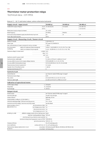
Supply circuit - Input circuit CM-MSS.x1 CM-MSS.x2 CM-MSS.x3
Rated control supply voltage U s A1-A2 24-240 V AC/DC 24 V AC/DC 220-240 V AC
A2-A3 - - 110-130 V AC
Rated control supply voltage U s tolerance -15...+10 %
Rated frequency 15-400 Hz 50-60 Hz
Electrical insulation between supply circuit and measuring circuit yes no yes
Power failure buffering time 20 ms
Supply circuit - Measuring circuit / Sensor circuit
Number of circuits 1 (CM-MSS.51: 2)
Sensor type PTC type A IEC/EN 60947-8
Max. total resistance of sensors connected in series, cold state < 750 W
Overtemperature switch-off resistance (relay de-energizes) 2.83 kW q 1% (CM-MSS.12 /.13 /.22 /.23: 2.7 kW q 5%)
monitoring switch-on resistance (relay energizes) 1.1 kW q 1% (CM-MSS.12 /.13 /.22 /.23: 1.2 kW q 5%)
Maximum voltage in sensor circuit 1.33 kW 2.5 V
4 kW 3.7 V
q kW 5.5 V
Maximum current in sensor circuit 3.7 mA
Maximum sensor cable length 2 x 100 m at 0.75 mm², 2 x 400 m at 2.5 mm²
Accuracy within the rated control supply voltage tolerance 0.50 % (CM-MSS.12 /.13 /.22 /.23: 5 %)
Accuracy within the temperature range 0.01 %/K (CM-MSS.12 /.13 /.22 /.23: 0.5 %/K)
07
Repeat accuracy (constant parameters) on request
Reaction time of the safety function < 100 ms
Hardware fault tolerance (HFT) 0
Control circuit
Control function see "Selection table CM-MSx range" on page 5
Maximum no-load voltage 5.5 V
Max. current 0.6 mA (CM-MSS.12 /.13 /.22 /.23: 1.2 mA)
Maximum cable length 2 x 100 m at 0.75 mm², 2 x 400 m at 2.5 mm²
Indication of operational states
Control supply voltage U LED green
Relay status R LED yellow
Fault message F LED red
Output circuit
Kind of output see "Selection table CM-MSx range" on page 5
Operating principle closed-circuit principle
Contact material AgNi alloy, Cd free
Rated operational voltage U e (IEC/EN 60947-1) 250 V AC
Minimum switching voltage / Minimum switching current 24 V / 10 mA
Maximum switching voltage / Maximum switching current see data sheet
Rated operating current I e AC-12 (resistive) at 230 V 4 A
(IEC/EN 60947-5-1) AC-15 (inductive) at 230 V 3 A
DC-12 (resistive) at 24 V 4 A
DC-13 (inductive) at 24 V 2 A
AC Rating (UL 508) utilization category (Control Circuit Rating Code) B 300
maximum rated operational voltage 300 V AC
maximum continuous thermal current at B 300 5 A
maximum making/breaking apparent power at B 300 3600/360 VA
general purpose rating 250 V AC - 4 A
Mechanical lifetime 30 x 10 switching cycles
6
6
Electrical lifetime at AC12, 230 V AC, 4 A 0.1 x 10 switching cycles
Maximum fuse rating to achieve short-circuit n/c contact 10 A fast-acting (CM-MSS.12, CM-MSS.13, CM-MSS.51: 6 A)
protection n/o contact 10 A fast-acting