
Page 2915 - Din prodcuts 2020
P. 2915
22/19
—
Quick product references
Protection and safety wiring diagrams
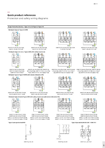
Surge Protective Devices - Type 1+2 12.5/Type 2/ Type 2+3
Multipole Type 2/ Type 2+3 SPD
OVR T2-T3 1N 20-275 P QS, OVR T2-T3 3L 20-275 P QS, OVR T2-T3 4L 20-275 P QS, OVR OVR T2-T3 3N 20-275 P QS,
OVR T2 1N 40-275 P QS OVR T2 3L 40-275 P QS T2 4l 40-275 P QS OVR T2 3N 40-275 P QS
Multipole Type 1+2 12.5 / Type 2 SPD with safety reserve (s)
Datasheet Surge Protective Device - 2010 - 01 2CTD432282F1701
OVR PLUS N3 40
Order code : 2CTB803701R0300
EAN Code : 3 660 308 51707 4
OVR T2 1N 40-275s P QS, OVR T2 3L 40-275s P QS, OVR T2 3L OVR T2 4L 40-275s P QS, OVR T2 4L 80- OVR T2 3N 40-275s P QS, OVR T2 3N 80-
OVR T2 1N 80-275s P QS, 80-275s P QS, OVR T1-T2 3L 12.5-275s 275s P QS, OVR T1-T2 4L 12.5-275s P 275s P QS, OVR T1-T2 3N 12.5-275s P
OVR T1+2 1N 7 275s P P QS, OVR T1-T2 3L 12.5-440s P QS QS,OVR T1-T2 4L 12.5-440s P QS Surge Protection Device Auto-Protected
QS,OVR T1-T2 3N 12.5-440s P QS
Electrical characteristics
Multipole Type 2/ Type 2+3SPD with remote indication (TS) Types of networks TT - TNS
Number of poles 4
Type / test class T2 / II
Type of current A.C.
Nominal voltage Un (L-N / L-L) V 230 / 400
Maximal continuous operating voltage Uc (L-N) V 320
Voltage protection level Up at In (L-N/N-PE) kV 2 / 1.5
Voltage protection level Ures at 3kA (L-N/N-PE) kV 1.1 / 1
Voltage protection level Up at 5kA (L-N/N-PE) kV 1.3 / 1
Voltage protection level Up at 10kA (L-N/N-PE) kV 1.6 / 1.2
Nominal discharge current In (8/20) (L-N/N-PE) kA 20 / 40
Maximal discharge current Im (8/20) (L-N/N-PE) kA 40 / 60
OVR PLUS N3 40 Follow current If A none
OVR T2-T3 3N 20-275 P TS QS,
OVR T2-T3 1N 20-275 P TS QS, OVR T2-T3 3L 20-275 P TS QS, OVR T2-T3 4L 20-275 P TS QS, Temporary OverVoltage Ut V 334 / 1200
OVR T2 1N 40-275 P TS QS OVR T2 3L 40-275 P TS QS OVR T2 4l 40-275 P TS QS ( L-N : 5s / N-PE : 200ms)
OVR T2 3N 40-275 P TS QS
Residual current IPE mA none
Multipole Type 1+2 12.5/Type 2 SPD with safety reserve (s) and remote indication (TS) Response time ns <25
Operating current Ic mA < 0,1
Short circuit withstand Icc at Un kA 15
Degree of protection IP 20
106
Integrated disconnector Yes (MCB)
Integrated thermal sensor Yes
State indicator Yes (MCB)
TS remote indicator - auxiliary contact Optional - S2C-H6R
91 ref 2CDS200 912 R0001
Mechanical characteristics
Wire range L/N
Solid wire mm² 2.5…25
OVR T2 1N 40-275s P TS QS, OVR T2 3L 40-275s P TS QS, OVR T2 4L 40-275s P TS QS, Stranded wire OVR T2 3N 40-275s P TS QS, 2.5…16
mm²
68
mm
OVR T2 1N 80-275s P TS QS, OVR T2 3L 80-275s P TS QS, OVR T2 4L 80-275s P TS QS, Stripping length L/N OVR T2 3N 80-275s P TS QS, 11
OVR T1-T2 1N 12.5-275s P TS QS, OVR T1-T2 3L 12.5-275s P TS QS, OVR T1-T2 4L 12.5-275s P TS QS, Tightening torque L/N Nm 2,8
OVR T1-T2 3N 12.5-275s P TS QS,
Wire range PE
OVR T1-T2 1N 12.5-440s P TS QS OVR T1-T2 3L 12.5-440s P TS QS OVR T1-T2 4L 12.5-440s P TS QS Solid wire OVR T1-T2 3N 12.5-440s P TS QS 2.5…25
mm²
Stranded wire mm² 2.5…16
Type 2 auto-protected SPD Type 2 Special 24/48 AC & DC - OVR 75 V
Stripping length mm 11
N L Tightening torque PE Nm 2,8
Miscellaneous characteristics
Stocking temperature °C - 40 to +70
Operating temperature °C - 20 to +70
Maximal altitude m 2000
Weight g 790
Color of Housing Grey RAL 7035
GND
Reference standards EN 61643-11, IEC 61643-1
OVR Plus N1 20 OVR Plus N3 20 OVR T2 2L 20-75 P
Operating diagram
22
ABB Lightning Protection Group